Here we are. looks like@pbjr Yes please, that would really help me out.
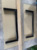
Specifically I'm interested in how fat the front faces of the bezel are - I've tried to draw some green lines to show what I mean. The sides, top and bottom. At the moment the sides are 9mm and the top/bottom are 19mm - how does that compare to the real thing?
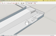
Overall starting to feel good - think I've found a way to split the model up and make it printable on my printer at home - Then when I've confirmed the sizing is right I might splash the cash as @Nimmers suggested and add to my next PCB order.
Also, if anyone knows anything about painting for 3D printed stuff now would be the time...


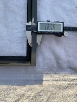
top 12.75mm
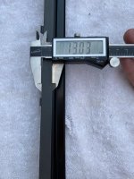
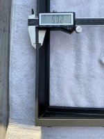
bottom 13
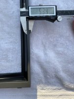
sides 5.3
If you need feel free to ask. First time I’m using this tool. Lol.

")