I've always been in love with the design of the knob for the Taito spinner, but AFAIK, there's nothing available online that comes close. (yes, I own 2 of the Egret Mini trackball/spinner controllers).
On top of that, that actual knob uses a roll pin instead of a screw-in clamp, so even if I had a pair of those in pristine condition, I couldn't trivially use it on a modern rotary controller, let alone any other custom project.
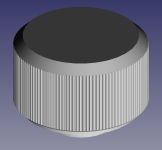
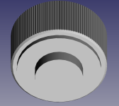
So I've been using calipers and FreeCAD with a spinner knob I picked up to try to replicate the dimensions/shape of the knob.
The only PITA is the grooves. Matching the shape is one thing but initially I didn't even know how many grooves there were.
I couldn't find any data online for this knob, so I took the one I had and... basically measured it by hand with my phone's macro camera, some painter's tape, and a ballpoint pen to drop a marker at each groove.
https://imgur.com/a/WHKfl51
Went around the whole thing and counted it by hand and I've got: 126 grooves.

Does that look right? Are there any obvious mistakes? I counted by basically using triangle shapes for binary counting (red was 1, dark blue 2, cyan 4, and yellow for 8 grooves) with some green rectangles to cordon on the groove I marked with ball point.
I couldn't find anything online with "taito spinner" and "126" on Google, so either I got the number wrong or nobody's ever counted. The image showing my work is 8K and at the bottom of the IMGur album I linked.
Eventually I'd like to have an STL that you can drop into a resin/PLA printer and then glue or solder-press in the metal inset, or even model in/print the inset and comission a lost material casting with aluminum.
In any event, the dimensions and groove count match so far. Now I need to figure out how to add insets to the top for the color disc XD

Edit:
Took some close-up shots of the physical knob: https://imgur.com/a/ErcMfvG
On top of that, that actual knob uses a roll pin instead of a screw-in clamp, so even if I had a pair of those in pristine condition, I couldn't trivially use it on a modern rotary controller, let alone any other custom project.
So I've been using calipers and FreeCAD with a spinner knob I picked up to try to replicate the dimensions/shape of the knob.
The only PITA is the grooves. Matching the shape is one thing but initially I didn't even know how many grooves there were.
I couldn't find any data online for this knob, so I took the one I had and... basically measured it by hand with my phone's macro camera, some painter's tape, and a ballpoint pen to drop a marker at each groove.
https://imgur.com/a/WHKfl51
Went around the whole thing and counted it by hand and I've got: 126 grooves.
Does that look right? Are there any obvious mistakes? I counted by basically using triangle shapes for binary counting (red was 1, dark blue 2, cyan 4, and yellow for 8 grooves) with some green rectangles to cordon on the groove I marked with ball point.
I couldn't find anything online with "taito spinner" and "126" on Google, so either I got the number wrong or nobody's ever counted. The image showing my work is 8K and at the bottom of the IMGur album I linked.
Eventually I'd like to have an STL that you can drop into a resin/PLA printer and then glue or solder-press in the metal inset, or even model in/print the inset and comission a lost material casting with aluminum.
In any event, the dimensions and groove count match so far. Now I need to figure out how to add insets to the top for the color disc XD
Edit:
Took some close-up shots of the physical knob: https://imgur.com/a/ErcMfvG
Last edited: