What's new

chacal231077

Grand Master
Joined
Dec 21, 2017
Messages
680
Reaction score
230
Location
France
Hi!:)


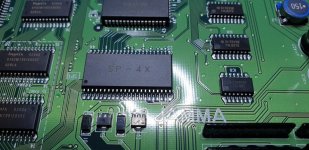
I did a first test, as Razoola had suggested to me at the time, to copy the bios 4 times for this version of PCB.

I did a clean job, but it didn't work.

Any suggestions for trying again?

I will order a SOP44 SMD socket connector so as not to damage the PCB

I programmed an MX26l6420MC-90 for the 4x bios.

Do you have an idea

Thank you

20220115_205652.jpg


20220115_205726.jpg

20220115_212031.jpg


20220115_213820.jpg


20220116_190843.jpg
 

Attachments

  • 20220115_205652.jpg
    20220115_205652.jpg
    188.7 KB · Views: 65
Last edited:
Is that a 3.3v chip in a 5v circuit?
 
maybe you need to byteswap the data
can you dump the original ?
 
That chip you used looks to be 64Mbit. The stock bios/unibios are 1Mbit, so you would needed to do 64x copies. You were likely told to use 4x copies because the bios chip on that pcb is 4mbit per mame and they assumed you would use the same size chip.
 
Ah Shit :D the code has to swim alone in a 64Mbit olympic pool lol :D

An SMS 44 SOP chip reference closer to the capacity of the bios to offer ?

Thank You :thumbup:
 
maybe i can help, what's the original chip number?
 
looking at mame, you need a 29f400
i have those somewhere.
you may even be able to use a 29f100 - i'd have to compare the pinout
 
checking the pads & tracks for flash that a rom wont need:

1 - not connected
2 - not connected
3 - ground (A17)
33 - connected to somewhere.
43 - not connected (/W)
44 - not connected (/RP)

so if A17 is grounded you can only use 256k - a 29f200 :)
you must connect 43 and probably 44 to the 5v rail - preferably through 10k resistors
 

Attachments

  • M29F200.pdf
    147.3 KB · Views: 102
checking the pads & tracks for flash that a rom wont need:

1 - not connected
2 - not connected
3 - ground (A17)
33 - connected to somewhere.
43 - not connected (/W)
44 - not connected (/RP)

so if A17 is grounded you can only use 256k - a 29f200 :)
you must connect 43 and probably 44 to the 5v rail - preferably through 10k resistors

I got a couple 29F200 today and your suggestion works as expected, thanks. I tied 43/44 via the 10k to pin 33 (BYTE) which the board already connects to Vcc to force 16 bit data mode.

I used

cat uni-bios.rom sp1-u4.bin > bios.bin

and can confirm that dip3 lets you switch between them.
 
Back
Top