What's new

US to ASIA B board conversion question

magicman

Student
Joined
Mar 12, 2025
Messages
46
Reaction score
13
Location
Coral Springs, FL
Hi, so I have a US Marvel vs Capcom rev 6 B board that was badly damaged by the battery leak. I picked up another rev 6 B board for Street Fighter Zero to convert Marvel vs Capcom to but I accidentally bought a ASIA B board. I only have a US A board. I've already transferred over the ROMS, the PAL G, configured the InfiniKey when I realized the different connectors on the bottom. Do I have to get an ASIA A board? Can I desolder the connectors and transfer them over ? BGS1 & 2 were socketed on the US board, they're soldered to the ASIA board, also spotted some caps not populated.


Basically, US B board to ASIA B board, same revision. Aside from the physical connection to the A board, is there anything different? Anything region locking?
 
The only difference is the connectors and they can be swapped as I have done this and can confirm it worked. It's a pain in the a.... though even with a desoldering station.
 
Agree the only difference is those connectors - there are 4 connectors with 96(?) pins per connector.

You dont have to change all the connectors of course (edit, see below I did not recall correctly, all 4 DO need changing). IIRC the Asia B board has one weird long connector, and 3 standard ones.
So thats only (only?) 96 pins to desolder the weird long one from the Aisa B board, 96 more pins to harvest a standard connector from a donor board, then 96 pins to solder back on.

96 (or 192) pins is reasonable amount of desoldering with a decent desoldering station. Might be worth looking at a .8mm nozzle to speed things up. Doing this by hand with braid/pump would be very time consuming and error prone

If you dont have a donor board to harvest from you could source a replacement connectors with the correct dimensions from here. Not identical to the OEM part, but electrically and mechanically compatible
https://www.digikey.co.nz/en/products/filter/connectors-interconnects/307?ColumnSort=0&ColumnSort=0&FV=7004c4,1600032,8d00002,ii3|2172,ffe00133,1140050&FV=7004c4,1600032,8d00002,ii3|2172,ffe00133,1140050&page=1&page=1&pageSize=25?k=eurocard connector&pageSize=25&pv589=25&pv589=25&quantity=&quantity=&s=N4IgTCBcDaIKYFcBOB7AxgQyQEwARpQDtC40AXFJEAGhBroF0BfIA&sf=0&sf=0&sv=0&sv=0
 
Last edited:
Desoldering all 4 connectors is a pain.

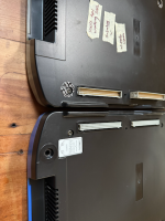
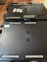
Asia connectors are exactly inverted from usa.
So a board connectors on b and b on a with one oddball length one.
Damn capcom.

If you change your mind I am in need of a working asia B.
I made this mistake, too.
 
Can confirm - one oddball length one AND the other three exactly inverted

IMG_0028.pngIMG_0027.png
Asia = top, USA = bottom in these photos

That being the case, you DO have to change all the connectors, 400 pins + 400 more pins for donors, + 400 pins to solder back on.

Way too much work for me...
 
Last edited:
I spent the better part of 2.5 hours yesterday just to remove 2 connectors from the old damaged US board. I still have 2 more to go and then on to removing the 4 connectors from the Asia board.

It's 96 pins, x 4 ... then I have to do it again on the new board 96 x 4. That's 768 pins to desolder, then 384 to solder again.

I'm using a Hakko FR-301 desoldering gun, I love this thing... but it is still taking forever lol

If I wasn't such a fan of the original MvC, I probably wouldn't be bothering. This is a ton of work, and if the logic chip by the battery hadn't been so badly damaged around the traces, I would have just swapped that over for much less work.


What I'm still not sure about is the socket BGS 1 & 2 on the old US board vs the soldered BGS 1 & 2 on the Asia board. Also a few 'CCX' caps populated on the US board that are not populated on the Asia board.
 
Spent about another hour going through removing the third connector. What I've found is that the battery leakage that affected pins on the connectors makes it much harder to desolder. I definitely plan to take some pictures of this whole process, so far all I have been doing though is just endless desoldering and cleaning of my desoldering gun.. not much picture worthy stuff going on yet lol
 
Ok finally finished transferring all the backplane connectors, I have pictures I'll be resizing and uploading this afternoon.

When I power it up, I just get solid color screens. One USA A board gave me a all RED screen (black on first boot), another USA A board gave me a AQUA BLUE or DARK BLUE screen. The A boards are known working as I tested them with Xmen COTA and SF vs Xmen. Anyone know what the colors mean?

I'm about to start transferring the CCX capacitors to see if it finally brings it to life.
 
Last edited:
The solid color screen usually means that the B board has suicided (battery has run dry).

If you have an Infinikey installed you may need to double check that it is installed correctly and that you are using the right settings for it to match your ROMs on the B board.
 
The solid color screen usually means that the B board has suicided (battery has run dry).

If you have an Infinikey installed you may need to double check that it is installed correctly and that you are using the right settings for it to match your ROMs on the B board.
Ok this is exactly what I thought it might be too.. wasn't sure if in fact the CCX caps were needed or not or if I needed to transplant the BGS 1 & 2 as well.

This was a Marvel vs. Capcom USA version, so MVCU is what I set the Infinikey to , and since its a rev-6 board, I jumped the non-5 jumper on it as well. I'll probe around to see what's not making contact
 
What color is the screen without a B board installed? Try powering it up first without a B board & see if you get the same colors/screens. It’s possible you might need to double check your soldering work.
 
What color is the screen without a B board installed? Try powering it up first without a B board & see if you get the same colors/screens. It’s possible you might need to double check your soldering work.
I have 3 USA A boards, 2 first boot with dark blue, then subsequent power cycles show a grey/blue sort of color . The third is black screen, then red every power on. I've checked all the soldering work, seems to all check out just fine.
Do you have the correct game code jumper's setting on infinikey? It kind of goes in reverse order (compared to openkey)

So for MVCU, code is 01010000, counting from 7 to 0, and I also jumped the jumper for a non rev-5 board.

Is there anywhere specific I can probe the board to know if something isn't getting power? Random probing does show voltage going through the B board.
 
I found JP10 on the board still coming up shorted even though I cleaned and practically destroyed the pads. I really don't know why. Two seconds from scrapping this project and waiting until I get an actual USA B board.


edit:
Some of the first 13 jumpers on the board have a tiny strip making contact, not a solder bead. I assumed all along that they either had solder beads or didn't to be shorted. I compared to my other boards and noticed this... but when I originally removed the old solder beads, I don't remember exactly which ones had bead on them or not.

I transferred the CCX caps and the socketed BGSB1 & 2 , no changes. These subtle differences make me wonder though if the board jumpers should be the same in terms of the small strip, not solder bead. Do I make sense?
 
Last edited:
I found JP10 on the board still coming up shorted even though I cleaned and practically destroyed the pads. I really don't know why. Two seconds from scrapping this project and waiting until I get an actual USA B board.
Some of the jumpers (including JP10) have a small trace between the pads so they are shorted by default and you have to cut the trace to disable.
 
Back
Top