What's new

ikefc

Student
Joined
Feb 4, 2023
Messages
24
Reaction score
29
Location
Spain
Hi guys,

This is my first thread in arcadeprojects,I´ve looked up here for many useful information so I´d like to share how I did the Vewlix stock monitor replacement in my recently acquired Vewlix L for anyone interested in,hope this helps.

I´ve done a lot of research to get ideas on how replace it on internet,including the UMB VESA 100X100 at Hadouken Arcade option,but well...it is not precisely cheap and also I live in Europe,so it wasn't an option since the beginning,the info on the net is also unclear so instead I did some inverse engineering doing tests and measurements and with patience is finally done!

MATERIAL:

1x Monitor --> https://iiyama.com/gl_en/products/g-master-gb3271qsu-b1/

1x VESA 100x100 adapter: https://www.amazon.es/dp/B0026UVVPK?psc=1&ref=ppx_yo2ov_dt_b_product_details

2x VESA 50x50 to 200x200 adapter: https://www.amazon.es/dp/B008KL72F2?psc=1&ref=ppx_yo2ov_dt_b_product_details

4x M8x30 Hexagonal nuts: https://www.amazon.es/dp/B086JN4VSQ?ref=ppx_yo2ov_dt_b_product_details&th=1

4x M8x70 Allen screws

4x M8 Wing nuts

4x VESA regular screws

4 x VESA 4x50 screws

STEPS:

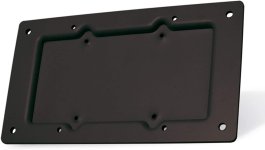
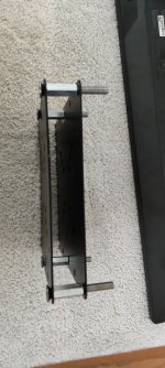
The VESA 100x100 hump format is key on this project,it provides an empty space to drill two kind of VESA screws.

1.jpg


This image is just for reference about how the Allen screws position:

2 (2).jpg


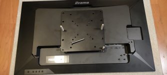
I did two additional holes (the original has not) in the two big VESA plates to fit the measures (200x200&100x100) in the existant cabinet holes and created a 2x VESA mount squeezing the screws and hexagonal nuts firmly,as you see the mount has the same measures as the hump in the stock monitor:
5.jpg

6.jpg

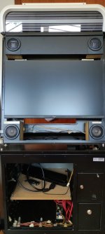
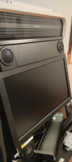
It is set in the cabinet using the two existent holes (just for position reference):

8.jpg


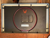
I set it in the monitor with the 4x VESA additional screws in the 75x75 holes: (Take care setting up the small screws to avoid damage in the plastic monitor!)

7.jpg
 

Attachments

  • vesa1.jpg
    vesa1.jpg
    40.8 KB · Views: 77
  • 4.jpg
    4.jpg
    128 KB · Views: 130
  • 3.jpg
    3.jpg
    77.7 KB · Views: 90
  • 2.jpg
    2.jpg
    44.8 KB · Views: 88
Last edited:
Part2 (10 max images per thread)

I´ve added 4x additional plastic adapters in the top of allen screws after some tests to fit it perfectly.

9.jpg

Fix it in the cabinet with the wing nuts (with some additional human help if possible...:D)
10.jpg

12.jpg

13.jpg

15.jpg

IMG_20230218_132011.jpg


And that´s all,it fits perfect and is very firm without any kind of modification in the cabinet also with the original frame,once set up you can readjust the position,angle etc... if needed using the wing nuts squeeze.

Perhaps isn't the most professional way to do this,but at least it works and is simple and cheap,so for me is perfect!

Don´t hesitate to ask me any question if you have doubts,I´ll try to help you.


Regards,
 

Attachments

  • IMG_20230218_131113.jpg
    IMG_20230218_131113.jpg
    97.2 KB · Views: 95
Last edited:
Nice solution!

I presume the monitor bezel/glass is not attached to the display/cab and you just place it in position?
 
Nice solution!

I presume the monitor bezel/glass is not attached to the display/cab and you just place it in position?
Exactly,I just put it on top and fits well,in fact I think is better for monitor ventilation,I´ll not add the glass because is a bit yellowed and this IPS looks amazing by itself.

I´ll upload some more pics with the bezel in for reference.
 
Last edited:
Nicely done! The Hadouken bracket looks really nice, but I always figured I'd just figure out my own solution when I got around to it. Seeing what you did is inspiring me to get to it. Definitely want to see your final pics with the bezel.
 
Nicely done! The Hadouken bracket looks really nice, but I always figured I'd just figure out my own solution when I got around to it. Seeing what you did is inspiring me to get to it. Definitely want to see your final pics with the bezel.
Thanks! It's a pleasure to help someone to do this

Here the pics with the bezel in:

3.jpg


1.jpg


As you see,here exists a minimum distance (1 or 2 mm),but it can be adjusted easily using the bottom wing nuts loosening or squeezing to fit it as desired. I´m not fully done with the cab yet.

8.png
 

Attachments

  • 3.jpg
    3.jpg
    51.5 KB · Views: 84
  • 4.jpg
    4.jpg
    75.1 KB · Views: 76
Last edited:
I ordered monitors and parts last night to take this on, thanks for inspiring me to get off my butt and do this, really wanted to upgrade before Street Fighter 6 came out.

I won't be using your method exactly, but a similar approach. I'd like to secure the metal frame to the monitor too, have some thoughts on that, see if it all works.

Curious to see what you come up with! ^^
 
Curious to see what you come up with! ^^
My plan—without having the monitors on hand yet to verify everything based on photos and measurements—is to laser cut acrylic brackets to adapt 100x100 to 100x200 with the right vertical spacing, and then used 3D printed spacers on the M8 screws to get the depth exact.

It will make more sense when it's all stacked, there are at least two pieces of acrylic here, but this is my to scale drawing for things that is in theory pretty accurate.

1677512190609.png


For the monitor frame my idea was to 3D print L clips that will take the stock screws from the side and hold down the monitor case.

I took apart one of my Blue Diamonds to take measurements and scaled photos of the monitor to get here, so I'm confident it's reasonable accurate. But nothing like having the real thing on hand to verify. Monitors should be here tomorrow along with enough M8 parts to make two of these. Once I get one dialed in should be much faster to duplicate for my second cab.
 
Sounds good!

I too would like to fit the frame to the display so the whole thing can be taken on/off as one unit. I like you're idea with the L clips. Removing the stock monitor and installing a slimmer replacement leaves a lot of useable space in that area

The stock screws used in the frame are a mix of M3 and M4 (IIRC) and so not the strongest of things which Is why I think the Hadouken mounts open out the holes and fit larger screws. I would like to avoid this if possible though and leave the

I think if you make multiple L clamps and use the center three bolts top and bottom and the central 'horizontal' bolts then that would be enough to support the fairly light monitor weight, even with small ~M3 bolts.

My idea was to CNC cut some thin steel plates to bolt to the inside top and bottom of the monitor frame and then use 2040 aluminum extrusion to brace across the back. Adapters/plates can then be easily fitted to various sides of the 2040 extrusion and fit the display to the 2040 section and then the 2040 section to the cab.

I've put off development of this as I need CNC access. It's something I could do at work but I was kinda saving it as a project for some upcoming toys later this year ^^

I do like your L clamp idea though and that's something I could be getting on with now. I'll be interested to see what you come up with, maybe we can bash some ideas about?

What monitors are you putting in yours? I've got a pair of LG 32GN550's to go in. Looking at your picture you may be using something similar. If it helps your development at all I've made a model of mine and uploaded a STEP214 of it [here].
 
What monitors are you putting in yours? I've got a pair of LG 32GN550's to go in.
LG 32GN650, so very similar, looks like they didn't change the case for it. They were a really good price for the specs, and I just didn't feel like I needed more for the application. Fighting games are very demanding on input lag, but not much else. No dark hallways, no big 3D panning like in FPS. The VA panels will be good for dark room play, which is pretty much all they'll see.

Ultimately I think I'm not super worried about everything being super strong. Once the monitor is installed it's very secure and it's not like I take it out often. So long as the L clip idea is enough to hold everything in place while I install it I think it should be sufficient. Just gravity and the cabinet frame honestly holds it all pretty well, nothing is actually floating free. I'll be careful in how I handle everything, won't try and pick it all up by the mount on the back of the monitor or anything dumb. Even just a press fit to keep it all lined up will make me feel better.

Thanks for the Step file! I don't think I really need it, but at one point I was very curious how deep the cutout area was for the inputs (looks like 7.8mm). It's very annoying to have them on the back, one of the other models I was considering had the DisplayPort connector right where I needed to put a bolt for the 100x200 mount. Was going to have to space things and use a right angle connector and couldn't tell how tight it was going to be.

If this all works I'm happy to share my source files and process.
 
Thanks for the Step file! I don't think I really need it
I lied, I actually took several measurements off it today, thanks! :D

Have prototype models for the clips ready, they're very basic but will hopefully get the job done. Will try and test tomorrow when my monitors come.


1677540213192.png
 
Was trying to explain the clip idea to my friend and he didn't see it, realizing that that screenshot of the models is confusing since they're on their backs. So made a quick drawing for him to demonstrate how they wedge in around the monitor case and hold it down. In theory!

1677561327514.png
 
Great stuff. I'm glad the STEP file was of some use. I look forward to seeing the result ^^

What are the three variants for? I'm guessing one is for the top/bottom edges and one is for the sides?

I had a look at my LG monitors last night and looked at the mounting holes in the frame. There are five bolt holes across the top/bottom and three on the sides. You could clamp using the centre bolt on the top/bottom but the clamp would need quite a short lip due to the central protruding section on the back of the monitor. 'You' might get away with having clamps on bolt hole positions 2 and 4 on the top bottom and then just the central one on both sides.

Are you threading the holes? Direct screw in / captive nut / insert nut?
 
So I had chance to have a bit more of a play tonight. The five and three bolt holes I was referring to are for the outer trim, not the actual monitor mounting points. These are all M3.

There are two monitor mounting points top and bottom and two on both sides of the inner frame. These are all M4 which gives me more confidence about using them for clamping over M3. Not that you would be able to apply enough force to shear off either of them....

I now see why you have three bracket designs as the mounting holes on the top, bottom and sides are all at different heights. Out of interest, what measurement did you get from the bottom for these? I measured 32.5mm, 25.5mm and 18.5mm respectively.

This is what I came up with. I just designed one and then changed a couple of the dimensions to suit the other two types:

i-4spvzLR-L.png


I've ordered some 10mm wide by 1.5mm gasket that I'm going to apply to the inside of the steel bezel to protect the edges of the screen and to keep any dust out. I've made a clearance allowance for this on the 'foot' of the bracket.

I also noticed that the thickness of the monitor varies by about 1mm around the perimeter so I've added some extra clearance to the underside of the 'finger clamp' and I'll use some of the foam gasket on the underside of the clamp to pack it out where necessary.

I've got some M4 insert nuts I'm going to insert them with my heat press. I've got plenty of black PLA so I'm just going to use that. I've got my slicer settings at three perimeters, 20% infill, and a 8mm 100% solid cylinder infill modifier around the M4 hole to give plenty of material for the insert. Looking at about an hour a piece with those settings which isn't too bad.
 
now see why you have three bracket designs as the mounting holes on the top, bottom and sides are all at different heights.
Right, missed that at first myself.

Out of interest, what measurement did you get from the bottom for these? I measured 32.5mm, 25.5mm and 18.5mm respectively.
I have 33, 25.5, and 18, so within .5mm of you.

I just got the monitors so time to do some real world testing instead of theorizing.
 
Yes, it's one thing looking at it on the screen, it's another thing when you go to try it for real, which is normally where I spot all my errors or things I had not thought about :D

How did you get on with your shiny new monitors? ^^

I had a fairly successful day all in all. Got the printer going about 7am and kept it going most of the day. Luckily I didn't need to re-print anything so I managed to get all 8 brackets/clamps done.

I started with the side pieces. I printed them on their side so that the potential shear plane is 90 degrees to the Z axis/print layers. it doesn't really matter for this job as the replacement monitor is so light and will be well supported by the eight brackets. I'm using M4 brass inserts and you can get away with printing the holes vertically but they are never perfect and so I prefer to print the holes undersize (3.5mm in this case, left in the picture below) and I then opened them up to the required 5.5mm size using my drill press.

i-wQ29h5N-L.jpg


A (very cack-handed) video of the last side bracket being installed:

View: https://youtu.be/TdDgAxXcIgE


The horizontal brackets are identical so that the monitor is centered. Luckily, just before moving onto printing the top/bottom brackets I realised that I had also made the spacing width of the bracket identical on both the top and bottom brackets. However, there is a strip at the bottom of the monitor which needs to be positioned below the viewable area and so the bottom bracket needs a smaller offset, and the top one needs increasing..

I positioned the monitor vertically where it needed to be and designed some new brackets to suit. I reduced the required width of both brackets by 2mm and made some spacers for them, this will allow me to adjust the vertical position by ±2mm without needing to reprint the whole brackets. I'll be able to check the position once I can the display on and get a test grid up.

i-MBHDMKt-L.png


All printed:

i-LFvjvMh-L.jpg


Using inserts gave me an excuse to use my insert press again, not that I needed one ^^ It's really fun to use and has come in useful for quite a few projects now:

View: https://youtube.com/shorts/HFKAUjVtbyc?feature=share


All fitted:

i-BZP8szQ-XL.jpg


I don't know if it was luck, or judgement, or a bit of both, but everything lined up and fit perfectly first time. I just need to wait for the foam tape to arrive tomorrow before I can do any more. I did leave some extra clearance in the height of the clamps to allow for the foam. It's supposed to be 1.5mm but that could be any where around there and it may compress too. I left some extra clearance so I can make some foam backed packers to slide under the clamp fingers and allow for a good fit/hold.

After that I can test fit in the actual cab. The clamps do feel really solid and you could quite easily get away with not needing the VESA>Vewlix adapter mount but I will make one. Being able to fit the monitor in the cab without the VESA>Vewlix adapter mount will actually make it easier to check some of the required dimensions.
 
That looks very familiar! :D

Short on time to document more right now, but close to trying to mount it.
 

Attachments

  • Vewlix-3D-mounts.jpg
    Vewlix-3D-mounts.jpg
    216.7 KB · Views: 83
Back
Top