What's new

Franco23444

Grand Master
Joined
Apr 24, 2020
Messages
1,183
Reaction score
926
Location
Nowhereland
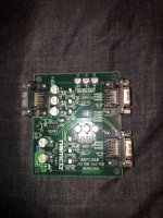
Hello everyone, I got this pcb in the mail today and I’m wondering what this pcb was used for and how does it function? I tried connecting a bunch of my arcade boards and it seems to do nothing. How can I get this thing to work? Where is it from?
 

Attachments

  • 5B96488F-C747-48D0-AFB2-FE12A0B27614.jpeg
    5B96488F-C747-48D0-AFB2-FE12A0B27614.jpeg
    403 KB · Views: 172
Looks like one of the linking PCBs used to connect two cabs together, only its missing the JVS and audio portion and it appears to only be a video splitter.
I had one for Vewlix, this is what it looked like...
4DauOSv.jpg


In Japan all VLX cabs have single player control panels, this is how you are intended to play SF4 (ie by networking two machines together with that PCB).
 
It doesn’t appear to work then. Doesn’t want to split video signals at all. Kinda disappointed because I wanted to use this to record gameplay off my arcade pcbs that don’t have another RGB vga port. In other words, the sync signal is out of wack.
 
Well it likely only works with 31khz sources, are you sure its "dead"?
It might do 15khz IF you separate the composite sync into H and V first?
 
Well it likely only works with 31khz sources, are you sure its "dead"?
It might do 15khz IF you separate the composite sync into H and V first?
I have tested it with both resolutions and 31khz doesn’t do anything but 15kHz shows sync issues. Also voltage of some sort seems to be leaking though the RGB lines that shouldn’t be present. It’s weird. Haven’t tried converting composite sync into HV sync yet.
 
Well, I tested it out and it does indeed work using HV sync. The thing is, I want to be able to use this using composite sync and my light gun games. How can I achieve that? Or the other way around? How do I make this thing work with composite sync instead?
 
Last edited:
Never mind, I figured it out. Since vga should have 5v, this converter uses that but some of my pcbs don’t. There is an unpopulated pin header on the pcb and of course, when I apply 5 volts, an image appears! So it’s solved!
 
Back
Top