I wrote an how to in the description of the video I posted on youtube :
View: https://youtu.be/gsnVawQdUa4
But whatever... here are all the condensed informations :
Important: you need a KI board, the KI2 board won’t work.
In the past, Midway offered an upgrade kit to operators that gives them the ability to convert an original Killer Instinct to KI2. The kit consisted of a set of 8 sound roms, a boot rom, a hard drive and his infamous IDE conversion board. While a KI board will work with the upgrade kit installed, this won’t work the other way round, ie. a KI2 board wouldn’t work with a KI HD and roms set.
Hence, it’s mandatory to have a KI board.
@DogP, from the Arcade Projects forum, provided a patch for the boot rom that gives us the ability to run the KI2 HD and roms on a KI board without the need of the (very rare) IDE conversion board. Download the patch from @DogP (https://www.arcade-projects.com/threads/killer-instinct-dual-board.5929/page-4#post-289917) and patch the “KI2 conversion Any IDE” rom.
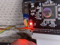
To switch from one disk to the other I used an IDE 44 pins to SD converter (https://www.aliexpress.com/item/4000333745167.html) with a 2in1 microSD adaptor (https://www.aliexpress.com/item/33040785519.html).
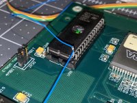
For the sound and boot roms you must use eproms with double the size of the original ones. Original roms are 27C040s, so you’d need 27C080s (https://www.aliexpress.com/item/32360913253.html).
Concatenate the rom files: do a copy /b ki_u10.bin + ki2_u10.bin ki_ki2_u10.bin for each rom and burn them to the eproms.
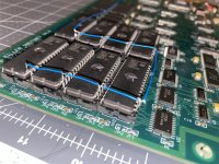
To switch from one bank to the other you must switch A19 (pin 1) from high to low. Insert the eproms into the PCB but leave pin 1 outside, daisy chain all the pins hanging out and connect them to a switch so that one position of the switch connects those wires to ground, and the other position of the switch connects them to 5V.


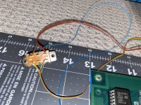
I used a DPDT switch to switch the eprom banks and the SD card in the 2in1 adapter at the same time, because the DPDT switch has 2 row of 3 pins for 2 different circuits.
One circuit is for the eproms, connect 5v and GND (tap them from the IDE adapter) on either side of the switch, and then connect the wire from the daisy chain to the middle.
The other circuit replaces the switch on the adapter. When you pull off the switch from the adapter there are 2 round pads and 1 square pad. To select the microSD card you have to close the circuit between either one round pad and the square pad.
SD-A
O O [ ]
|_____|
SD-B
O O [ ]
---|__|
If you get an acrylic case, like the one from Emiliano Arlettaz (https://github.com/emilianoarlettaz/arcade-pcb-case), you can print my switch holder (files here https://www.thingiverse.com/thing:5026931) designed for this DPDT switch : https://www.digikey.com/en/products/detail/c-k/SS-22F02-DG-6-L/2747185 and 10 mm high steel stands.
But whatever... here are all the condensed informations :
Important: you need a KI board, the KI2 board won’t work.
In the past, Midway offered an upgrade kit to operators that gives them the ability to convert an original Killer Instinct to KI2. The kit consisted of a set of 8 sound roms, a boot rom, a hard drive and his infamous IDE conversion board. While a KI board will work with the upgrade kit installed, this won’t work the other way round, ie. a KI2 board wouldn’t work with a KI HD and roms set.
Hence, it’s mandatory to have a KI board.
@DogP, from the Arcade Projects forum, provided a patch for the boot rom that gives us the ability to run the KI2 HD and roms on a KI board without the need of the (very rare) IDE conversion board. Download the patch from @DogP (https://www.arcade-projects.com/threads/killer-instinct-dual-board.5929/page-4#post-289917) and patch the “KI2 conversion Any IDE” rom.
To switch from one disk to the other I used an IDE 44 pins to SD converter (https://www.aliexpress.com/item/4000333745167.html) with a 2in1 microSD adaptor (https://www.aliexpress.com/item/33040785519.html).
For the sound and boot roms you must use eproms with double the size of the original ones. Original roms are 27C040s, so you’d need 27C080s (https://www.aliexpress.com/item/32360913253.html).
Concatenate the rom files: do a copy /b ki_u10.bin + ki2_u10.bin ki_ki2_u10.bin for each rom and burn them to the eproms.
To switch from one bank to the other you must switch A19 (pin 1) from high to low. Insert the eproms into the PCB but leave pin 1 outside, daisy chain all the pins hanging out and connect them to a switch so that one position of the switch connects those wires to ground, and the other position of the switch connects them to 5V.
I used a DPDT switch to switch the eprom banks and the SD card in the 2in1 adapter at the same time, because the DPDT switch has 2 row of 3 pins for 2 different circuits.
One circuit is for the eproms, connect 5v and GND (tap them from the IDE adapter) on either side of the switch, and then connect the wire from the daisy chain to the middle.
The other circuit replaces the switch on the adapter. When you pull off the switch from the adapter there are 2 round pads and 1 square pad. To select the microSD card you have to close the circuit between either one round pad and the square pad.
SD-A
O O [ ]
|_____|
SD-B
O O [ ]
---|__|
If you get an acrylic case, like the one from Emiliano Arlettaz (https://github.com/emilianoarlettaz/arcade-pcb-case), you can print my switch holder (files here https://www.thingiverse.com/thing:5026931) designed for this DPDT switch : https://www.digikey.com/en/products/detail/c-k/SS-22F02-DG-6-L/2747185 and 10 mm high steel stands.
Last edited:


")