What's new

hatmoose

Champion
Joined
Mar 25, 2021
Messages
1,090
Reaction score
2,271
Location
New Zealand
This guy had been kicking around in my big box of junk since January.

I bought the A+B board set for approx $US120. The A board worked perfectly right away - and $120 for an A board isnt a terrible price in my country - so I was happy to call it even at that point. The B board had a leaky battery which was beyond my ability and tools at the time so I put it to one side to fix later. Later has arrived

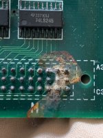
Here was how it looked back in Jan - most of the damage was around the battery 10L and 10M, a little bit up by CN6, and a little bit up by the jumpers JP4
IMG_4199.jpegIMG_4200.jpeg

After a quick clean with some IPA it looked like this


Then I gave it a bath in vinegar, then in deionised water, then in IPA - after some time in the dehydrator it looked like this
IMG_8906.jpegIMG_8908.jpeg

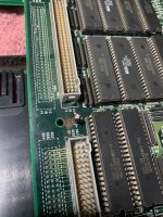
So the 74LS254 at 10M is had it, but other than a tonne of traces and vias it looks like this board may have escaped serious damage

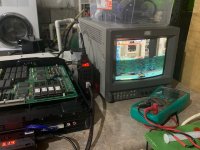
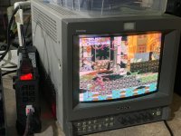
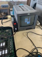
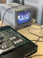
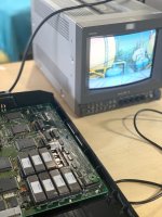
So I patched up all the bad traces that I could find, repaired all the busted vias, and put an infinikey on and... It boots, and passes tests even!
IMG_8894.jpegIMG_8904.jpeg

Next thing is to fix the sprites (there are none), music (there is none of that either), and sounds (present but crackly)


I'll probably see if I can find a donor to replace 10M and see if that improves the situation.

For those that come after and may read this I took a lot of inspiration from here
https://www.arcade-projects.com/threads/cps2-a-board-restoration-from-death-to-life.12444/
and here
https://fluxcore.nz/blog/cps2-repair-battery-damage
and here
http://forum.arcadecontrols.com/index.php?topic=160428.0
and of course the many awseome threads on this very board
 

Attachments

  • IMG_8903.jpeg
    IMG_8903.jpeg
    199.3 KB · Views: 171
  • IMG_4203.jpeg
    IMG_4203.jpeg
    239.1 KB · Views: 170
  • IMG_8890.jpeg
    IMG_8890.jpeg
    161.8 KB · Views: 161
  • IMG_8886.jpeg
    IMG_8886.jpeg
    175.8 KB · Views: 184
Replaced the 74LS254 at 10M. I have a plentiful supply of spares so I didn't try very hard to save the old one. I didn't want to risk more damage to the pads with hot air so I removed the old chip with clippers. The two pads on the bottom right were gone altogether - but all the others were still sound
IMG_8913.jpegIMG_8915.jpeg

Harvested another 74LS254 off a broken A board and replaced the damaged one, ran some bodge wires from those missing legs to the nearest via and...
IMG_8917.jpeg

Sprites!
IMG_8919.jpeg

But the sprites are not quite right - it's like they have been drawn at half resolution - and sometimes they are drawn with vertical bar glitches.

Jubilee and rogue look like they are in 120p
The capcom logo is super chunky
Ryu and Magneto are drawn correctly, but at low resolution - it's like every second line is skipped and doubled
Ken and gambit are drawn correctly but at low resolution - you can see the line doubling thin with the text at the bottom of the screen
rogue and sabretooth have weird glitches,
IMG_8944.jpegIMG_8932.jpegIMG_8947.jpegIMG_8937.jpegIMG_8930.jpeg

So solid progress, but still some work to do.
I'm guessing the glitches are caused by damage to the address lines for which ever mask rom those characters are on. I'll reseat all the ROMS and start probing the pins for continuity to see if I can find the damage

but the "low res" thing has me stumped - anyone ever seen sprites like this before? It's quite a cool effect - I wish I knew how to re-create it on purpose
 
Between January and now the CPS2 B board has basically become a solved problem. Full details in this thread
https://www.arcade-projects.com/threads/extreme-cps2-battery-damage-repair-round-3.16823/page-2
And fully reverse engineered here
https://gitlab.com/loic.petit/cps2-reverse

So if (like me) you want to learn about PCB repair and (like me) missed the initial drop of this info, here it is again.

With this awesome reference in hand I’ll start probing. The DL1927 is going to be the prime suspect. I thought it had escaped damage but either there is a bad pin, or I missed one of the traces when I was patching up the acid damage. Either way, knowing exactly where to look makes the task much less scary - thanks team!
 
Finally got around to finishing this one off today

There were two main problems remaining
1) Entire sprite layer was being drawn at half resolution - everything looked super chunky
2) Glitchy character sprites in the game for some characters.

The half resolution thing was actually a really cool effect - I had never seen anything like it before
IMG_0421.jpegIMG_0422.jpeg

@WydD has done some amazing CPS2 work which I really appreciated - thank you! I used his sheet and checked continuity on all the pins on the 1927
https://docs.google.com/spreadsheet...knL34eWvkaVA7-mJ8i6F27lmk/edit#gid=1029199072
It took me a while to figure out how to read the sheet - the breakthrough (for me) came when I realised that the pins of some chips were labeled by function, just like the neogeo pinouts.

Because the problems were with sprites and characters I guessed that CGA(DL-1927) and CGD(DL-2027) were probably the best place to start
CGA = character generate address?
CGD = character generate data?

The weird half resolution in the sprite layer was a broken trace between DL-1927 pin #57 and DL-2027 pin #75
The glitchy sprites for some characters was a broken trace between 1927 pin #53 and the PAL at J9 pin #2

Both of the faults are in this photo - rotten vias. This is the second time that visual inspection - even with a microscope, was useless. I never would have found these in a million years without the wiring sheet.
IMG_0426.jpeg

And here they are fixed, again not much to see
IMG_0436.jpeg

Outcome = complete success, the game now looks, sounds and plays perfect.
 
I have a X-men Vs Street Fighter that shows lines in certain sprites, all roms are OK. I'm going to try to decode the infos in this thread to see if I can figure out what's the problem. Thanks a lot for the infos and links
 
I have a X-men Vs Street Fighter that shows lines in certain sprites, all roms are OK. I'm going to try to decode the infos in this thread to see if I can figure out what's the problem. Thanks a lot for the infos and links
Do you think there's damage from a leaked battery? If not, it might just be a poor connection between A board and B board. I have a MSH vs SF like that where I really gotta make sure A and B board are connected or I get glitches in some sprites. You can always try taking the boards out of the housing to be sure you get a good connection.
 
Another one, AvP this time

I bought this for $US25 - seller was very honest "Battery damage is a certainty, there is brown liquid leaking out the sides". the stench when I opened this thing was overpowering...
IMG_5777.jpeg

But as batter damage goes ive seen worse - all of the big customs are intact, everything else is just (lots and lots and lots of) time. It probably would have been cheaper and faster to drive uber for a couple of days and use the $ to buy a tested working AvP. But nothing is foolproof for a sufficiently talented fool.

Going to need some new zener diodes and 245's
IMG_5778.jpegIMG_5780.jpeg

And some of the EPROMS/sockets need work
IMG_5783.jpegIMG_5782.jpeg

But the really time consuming bit will be this, the chip itself is OK, There are at least 20 vias in this pic that will need fixing.
IMG_5779.jpeg

So from here my approach will be to wash it in water to clean the filth, wash it in vinegar to stop the corrosion, wash it in IPA to stop the vinegar, then start work on repair.
 

Attachments

  • IMG_5781.jpeg
    IMG_5781.jpeg
    119.2 KB · Views: 72
That AvP hurts to look at - you’ve got some serious repair work ahead of you, but it sounds like you’re up to the task. Good luck! :thumbsup:
 
Some of the Eproms lost some legs to corrosion, perfectly possible to fix them with bodge wires. But the appeal of over-engineering the hell out of a solution was too strong to resist. This magnificent beauty deserves better than bodge wires!

I had been goofing off with the new features of Kicad 7.0 (true type fonts, greatly improved image editor) and decided to make some PCB's to reinforce the damaged EPROMS and give me a reversible method of soldering to what remains of the legs. I stole this idea from Ack and his awesome Kabuki openkey project. Needs a socket with "hollow legs" like this one. https://www.digikey.com/en/products/detail/adam-tech/ICM-640-1-GT-HT/9832971 and .8mm PCB.

Screen Shot 2023-10-19 at 9.59.18 PM.pngScreen Shot 2023-10-19 at 9.59.31 PM.png

In the extremely unlikely event that anyone wants to solve the same problem, gerbers are attached.
AVP better.zip = alien and text as standard silkscreen - if you want something that works I would go for this one
AVP more better = experiments with internal copper layers, using TTF as a footprint then cutting a negative silkscreen layer, other weirdness - this one is just for fun
 

Attachments

  • AVP better.zip
    148.2 KB · Views: 47
  • AVP more better.zip
    148.4 KB · Views: 49
Saw that board on TradeMe and altough I've fixed much worse, thought: not worth my time (and I already have the CPS2 multi anyway).
Good luck with the rescue, I wish I had that much free time.
 
The PCBs came out not at all like I was expecting, but actually pretty cool

This one was supposed to have an alien shaped hole cut in the solder mask, exposing the copper. But somehow my setup cut through both the mask and the copper exposing the substrate. The substrate is a kind of sickly translucent green color which is perfect for the alien. In hindsight it would have been even cooler if I had cut the mirror in the top which would have been even more translucent on a board that thin.
IMG_5952.jpeg

The “All Black” one was supposed to have the alien on the silkscreen layer, but it ended up on the copper layer with mask over the top. It’s quite a cool effect but the black solder mask makes it hard to see.
IMG_5951.jpeg

So still some more kicad7 to learn, but for this project I’m extremely pleased with the “translucent substrate” alien.
 
Project “alien sarcophagus” is completed, all EPROMS saved, as clean as I dare without damaging the stickers.

Now the minor issue of the board…
 

Attachments

  • IMG_5963.jpeg
    IMG_5963.jpeg
    130.4 KB · Views: 52
  • IMG_5964.jpeg
    IMG_5964.jpeg
    134.9 KB · Views: 50
  • IMG_5962.jpeg
    IMG_5962.jpeg
    130.6 KB · Views: 48
Success!

Clearly the Capcom engineer that laid out the CPS2 mainboard was being paid by the square mm. There is absolutely zero clearance between the sockets, they are packed in there *tight* and my Alien Sarcophagus PCBs were a very tiny bit too big.
It is possible to pay JLCPCB for "high precision" boards that fit perfectly, or its possible to manually sand them down at extreme risk to personal health.
IMG_6921 (1).jpeg
Patched up all the obvious trace damage, and it boots first time!
IMG_6926 (1).jpeg
Sound OK, Backgrounds OK, Looks like bad sprite addressing. Patched some less obvious trace damage, nearly there
IMG_6928.jpeg
Fixed the sprite addressing, looks like bad program address lines. Got bored and decided to find out what happens if you remove the program roms - this is what happens. I've never actually seen the "memory viewer" screen on a CPS2 before so that was a fun Easter egg
IMG_6932 (1).jpegIMG_6931 (1).jpeg
Resisted the urge to spend the rest of the night messing around with the memory viewer. Came back and patched the last of the program address trace damage, success fully working! Another Capcom Classic saved.
IMG_6933.jpeg

Now that CPS2 has been fully reverse engineered, fixing even the most appalling battery damage is only a matter of (a lot of) time.
Full Schematics in Kicad format are here
https://gitlab.com/loic.petit/cps2-reverse
Or if you are like me and suck at Kicad and forget how to read schematics; this is the "what beeps with what" cheat sheet - absolutely awesome CPS2 resource when I just want to know which probe to poke where
https://docs.google.com/spreadsheet...knL34eWvkaVA7-mJ8i6F27lmk/edit#gid=1029199072

Coming (much much later) on my CPS2 repair bench I have fixing other peoples repairs. SFZ3 with a failed reflow on one of the big customs. A failed conversion to SFZ2, and (you guessed it) more battery damage on COTA
 

Attachments

  • IMG_6934.jpeg
    IMG_6934.jpeg
    97.9 KB · Views: 32
  • IMG_6927 (1).jpeg
    IMG_6927 (1).jpeg
    105.7 KB · Views: 36
Back
Top