What's new

sonic323

Student
Joined
Mar 28, 2021
Messages
47
Reaction score
32
Location
Slovakia
Chassis Nanao Ms 9 - 29

Maybe someone can advise where to look for the error..
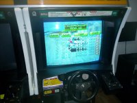
I bought a Sega Rally twin, I've had it for 2 years.
Both monitors had a vertical collapse, I fixed them by replacing them (vertical chip) and replaced all the capacitors.

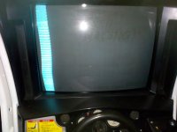
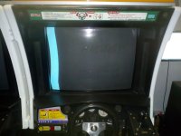
They worked very well, only the right one started doing this after cleaning the chassis:

I tried replacing the remote board
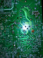
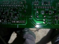
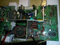
Remelted the solder on the chassis
Change the neck board from a good monitor and still the same error,
the potentiometer( chassis )(Horizontal expansion controls only a little).
Please, can someone advise where to look for the error?
 

Attachments

  • IMG_20220901_194921.jpg
    IMG_20220901_194921.jpg
    107 KB · Views: 107
  • IMG_20220205_075138.jpg
    IMG_20220205_075138.jpg
    162.1 KB · Views: 102
Last edited:
First, let me just say that is an awesome machine in minty condition. Other than the monitor obviously. Well, I would start by looking at all the pots on the chassis and remote board. Deoxit them and rotate back and forth, returning to the original position. You have B+ but check where it's at to be safe. Flyback is working, Vertical Deflection seems to be working. Horizontal Deflection could be the problem or it could be horizontal hold/phase? Check if the HOT is shorted?

Does the twin setup like that have 2 separate computers? can you try swapping the input source to make sure that the problem is in the monitor chassis and not on the game PCB?
 
Thank you for your reply, I really appreciate it..
After purchasing the machine, I completely restored it.
(Game) On one side it carried sound and on the other side it displayed a checkerboard pattern.
Fortunately, they were only defective Eproms (when I started exchanging them, I found out which ones were defective).
And the sound is already working (side one) and the other side boots the game fine.

(I only cleaned the chassis with a small dust brush and I had to loosen something..)

I will try to check the potentiometers
I will try to change the game boards.
I will measure the B+ voltage

And then I'll let you know.

Well thank you
 
check the rgb input wires and the yoke wires as well. if something got loosened during dusting that could be it? is the neck board firmly seated on the pins?
 
Hi, Thanks for your help


So far I have checked the B+ voltage, it was 114v, I increased it to 119v

Potentiometers:

H.H.24 and SPC24, I tried all of them (chassis and remote board)
I hardly respond at all..
Vertical potentiometers react up, down they react well.
The board on the neck, I tried to change it before and the result was the same..
And I tried to change the remote board before and still the same..
I tried to change the game boards and still the same result..

The stirrup approximates me:
Blue, red cable 1.2 ohm
Immediately, yellow cable 7 Ohm

I read somewhere that the transistor could be bad:

Q508, which is 2SD1944. I will try to change it from a still working chassis and let you know.

I still have to check (HOT).
 
Last edited:
Hi,

Here is a picture when the monitor was still working.
It is slightly darker than the left monitor, but that is probably due to the tube, I already changed the heating resistance on the right one from 3.3 ohm to 1 ohm, so the image is a bit clearer.

So far, no progress.

I replaced the transistor Q508, 2SD1944 from the working chassis and no change..

I replaced the Big transistor (HOT) from the functional chassis and no change..

I don't know which parts could be replaced to fix this problem.

I will try to measure all the parts and compare the data with the functional chassis..
 

Attachments

  • IMG_20220412_190515.jpg
    IMG_20220412_190515.jpg
    120.9 KB · Views: 66
Last edited:
Well, at least you know what's not the problem :)

I think since you tested and replaced the HOT with a known working one that the horizontal deflection is probably working ok. I think also that because there was no response from the H.H.24 pot that there is just no sync signal at all. You should be able to change the picture dramatically if there is a sync.

SPC24 is the pincushion setting, so there probably is a noticeable effect but only when the monitor has full and stable deflection.

because you tried using the other side's computer, you know a good signal (RGB and Sync) are being sent out. So there must be a sync failure somewhere on the chassis.
 
Thanks for help,

It will be something with the synchronization, I had to loosen something while cleaning, either the capacitor or there will be a cold connection somewhere, or a bad resistor that controls the synchronization. Or the cable that leads to the neck plate (I will try to measure the continuity)

I will compare with a functional chassis

I'll let you know if I find anything out.

Well thank you
 
Hi,

Thank you for the info,
Yesterday I just registered on (arcadeotaku ), so I still don't have a registration.
It looks like a similar bug to what I have on this chassis.

I have no success with the repair yet.

I tried putting the wrong chassis on the left side and still the same result.

At least I know that the caliper on the right monitor is fine.
and the cables on the right side in the machine are fine

Cable to the neck plate (continuity is good)
 
Last edited:
Hi

No success yet

I changed (list)

Voltage B+ ok
Q508,2SD1944
HOT
LA7853
AN5551 @ U450
Flyback
High voltage capacitors (around the Horizontal output)
Neck plate
Game boards (does it even without a game board)
I also found a bad connection on one capacitor to ABL, but it didn't help
Fused joints, checked

Everything was changed with a good chassis and I have not (changed back) them again.
The functional chassis always works at 100 percent, so these components is not Bad.

I just didn't change (Mitsubishi Chip), (Ukvac forum)I read there that the change didn't help.

It's not even a Flyback, it was replaced with in good (chassis)

The bad chassis is revision 05A00585D1
The good chassis is revision 05A00675C1

I can still measure each other, but there are small differences between them..

If anyone has an idea, let me know.. Thank you
----------------------------------------------------------------
The picture shows the component changes, which are 100 percent good..
 

Attachments

  • IMG_20220907_094219.jpg
    IMG_20220907_094219.jpg
    228.7 KB · Views: 59
Last edited:
H.H.24 reacts only a little, almost not at all, but if you turn the potentiometer more, for example to left, the monitor turns on the protection and turns off.
The picture is as if stretched to the left.
I suspect a bad capacitor (electrolytic). The small ones.
I have to order small 1uf, 22uf, I don't have them at the moment
 
I thought you said you replaced all the caps? You think one of the new ones went bad? I still think you are having an issue with your signal or sync?

sorry it's being annoying but at least you will feel very accomplished once it's fixed.
 
Hi

When I bought this machine, the monitor had (vertical collapse). So I replaced all the capacitors (electrolytic) as soon as possible and then I installed a new vertical chip (LA7837).
And the monitor started working.
So the capacitors are about 2 years old.

I also think that there is a problem with synchronization.
I have two revisions of the chassis, so the resistance values (small) are almost exactly the same (underside of the chassis).
In just one part, I found about 7 small resistances, which have larger differences in values.
It's just a different revision of the chassis, so it can be correct..

The capacitors are exactly the same values as the floods had, only the small ones are not 105 but 85 degrees and have different dimensions, so I had to modify them (soldering) before.


When nothing is connected (game board) input signal, the monitor looks similar, but the pass is white
 

Attachments

  • IMG_20220910_063343.jpg
    IMG_20220910_063343.jpg
    118.4 KB · Views: 53
Last edited:
Hi,
Good news for me, the monitor is working.
After almost a week of replacing and trying?(, I managed to fix it..

At the same time, it was such a banal problem but difficult to detect.

Interrupted track (miniature).

Later in the evening I will give a picture where exactly.
Thank (KaPH33n) for the help, I appreciate it


Working Monitor:8o:thumbsup:
 

Attachments

  • IMG_20220912_124350.jpg
    IMG_20220912_124350.jpg
    158.2 KB · Views: 62
Last edited:
The interrupted track starts at the resistor and connects to the Flyback, passes under the chassis and connects to the pin (long track).
So I think that a bad connection on the Flyback caused this failure.
The monitor works, so I made a prime connection via cable.
 

Attachments

  • IMG_20220912_132358.jpg
    IMG_20220912_132358.jpg
    292.4 KB · Views: 96
  • IMG_20220912_132945.jpg
    IMG_20220912_132945.jpg
    155.4 KB · Views: 97
great news! was that trace part of the sync circuit? I guess it doesn't matter as long as it's fixed. that's great that you were able to visually see how it connects and fix it without schematics or anything.

now like i was saying before... how accomplished does that make you feel? Like you're almost a god haha. Sometimes it's a true high. I fixed my space shuttle pinball today, on location, by repairing the original power supply.
 
Hi,

It was a complete coincidence to find this error.

It was a joy when the monitor suddenly came on.8o
After so many component changes and measurements (SMD Resistances, etc..)
The vertical collapse is quite well documented.
But is my monitor fault. (horizontal), I didn't see anything anywhere.
Before, I read how the Flyback works, it was written there, the ( Flyback is often connected to the horizontal circuit) , so I suspected the Flyback. But I had already changed the Flyback, so I checked individual paths leading to the Flyback and suddenly I found an interruption..
I also suspected Synchronization, but (output) when the error was there even without an input signal.

(When checking the chassis, I also found a bad trace on (ABL). Which did not work before (before the failure) and the potentiometer is now responding.)

Measuring tracks, it was just a coincidence to find this error.

Congrats on the Pinball fix and thanks for your help
 
Last edited:
I also had a problem with the voltage source in this machine. The capacitors (leakage of electrolyte) were bad, which shorted the high voltage to 5V. Everywhere I measured the voltage, game boards, sound boards, etc., I measured 230v. So into the flood case of the source I installed an ATX power supply and grounded the third pin. It looks like the original, only the ATX power supply is inside.
These flood sources can no longer be repaired, it's like a ticking time bomb when the game boards are damaged
 
Back
Top