What's new

Kujako

Grand Master
Joined
Jun 3, 2020
Messages
1,319
Reaction score
778
Location
USA, California
Can't find any documentation or service manuals, no idea how these work. But I have a dual slot main board, camera, wiring harness and some carts. How bad can it be?

Printer may be an issue, but since it's a serial "remote" emulator for a medical s-video printer I'm thinking I can worry about that once I get anything outputting.

1708643285443.jpeg
 
In the arcade community, there are no dumb ideas, just expensive ones. Good luck with this!

So far, not been too expensive. Only into this for a couple hundered. That may change if I get a printer since rolls of the sticker paper seem to be over $150 USD. Thinking a better option would be to use the standard non-sticker paper for these printers (around $30 a roll) and a "sticker maker". But that's a concern for once I get it working. From what I've been able to read, I should be able to trick it into a "printer ready" state by shorting a couple pins on one of the printer connectors (there's a mini din 9 cable that's the printer control and a phono jack that's the printer status).

First task, power and RGB output.

Right to left:
  • 5v power in has four pins, two ground and two +5v. However everything is bound together. So both grounds and both +5v are connected. It's not two separate feeds.
  • Next to the +5v input is the RGBS output. Exact pin-out is missing from the Neo Geo Development wiki. But it's easy to discern from the wiring harness.
  • Then we have the bank of S-Video in and out ports. Not 100% sure why there are so many... but one connects to the camera and another connects to the printer.
  • After that we have the flash control wiring. Doubt I'll wire this up.
  • Coin input.
  • Coin counter LED output.
  • Control panel. Not sure of the pin ordering, but ground is easy to determine so I can just go by trial and error.
  • 12v input. This is only needed for sound I think.
Then on the left side (right side when facing the unit) we have the camera control ports.
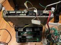
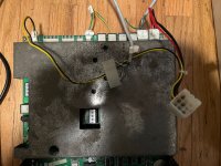
These two slot units are weird looking though with the stacked cartridge slots.
IMG_1749.jpegIMG_1748.jpeg

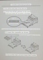
All seems manageable! Unfortunately still only managed to find the one page from a manual (I translated it as best I could).
IMG_1734.jpeg
 
Last edited:
Looks like I don't have the power wiring for the camera, but it should just be +5v.
 
Camera's working after building a harness and powering it from my bench supply.
1709216330984.jpeg


Far as I can tell, it only uses 5v and the center pin is unneeded. No idea what the potentiometers on the controller board do and the composite output seems to serve no purpose.
1709216389206.jpeg
 
Last edited:
Removed the small bit of masking tape off the camera, and it took the paint with it... anoying.
1709299337458.jpeg


Will wire everything up and try turning it on this weekend, if no one hears from me there was a fire.
 
Far as I can tell, it only uses 5v and the center pin is unneeded. No idea what the potentiometers on the controller board do and the composite output seems to serve no purpose.

composite output works fine for me? (thanks for that pinout!)

IMG_1090.jpg


IMG_1092.jpg

RV53 appears to be tint / color
RV52 appears to also be about color: cold / hot
RV51 not really sure what it does.

there's also a little S001 switch on the side which, again, not so sure what it does
IMG_1093.jpg


any other way I can help? :)
IMG_1091.jpg
 
Last edited:
  • Like
Reactions: nem
composite output works fine for me? (thanks for that pinout!)

RV53 appears to be tint / color
RV52 appears to also be about color: cold / hot
RV51 not really sure what it does.

Oh composite works, it just seems to not be used by anything.

Thanks for the pot info, will reach out if I hit any blockers that you might help with.

Just fake the interface and upload to instagram instead :)

That's kind of the idea... if I can capture the s-video output that would otherwise go to the printer.
 
well ... I'll let you move on now cause I think I'm done: this is what I get with only the svideo out plugged in (cause svideo cable have been gone a while! hard to dig 'em out) :
I *think* it's the attrack mode cause it blinks to something similar but just black and white after awhile and back to this. there are no sounds

IMG_1100.jpg


the board / cart (there are pots in there as well)

IMG_1101.jpg


IMG_1102.jpg
 
Last edited:
well ... I'll let you move on now cause I think I'm done: this is what I get with only the svideo out plugged in (cause svideo cable have been gone a while! hard to dig 'em out) :
I *think* it's the attrack mode cause it blinks to something similar but just black and white after awhile and back to this. there are no sounds

IMG_1100.jpg


the board / cart (there are pots in there as well)

IMG_1101.jpg


IMG_1102.jpg

Hum... that's not good. Are you showing the output of the RGBS or the S-Video?

As for the pot on the main board, it's in the audio section so my assumption was it was volume.

I'm checking over all the power harness wiring I have before I try to turn mine on (I have two main boards, a single and a dual slot. Both in unknown condition). Looks like for some reason someone crimped on some 220v 5a marine fuses to the power cables coming out of the power supply hook ups. Very weird, and falling apart. So thinking I'll just bypass those and reconnect the wiring directly.
1709323599214.jpeg
 
Looking to see how this works out! I might have a neo print motherboard somewhere. Thanks for sharing your progress!
 
I have one as well if someone needs a neoprint motherboard for some reason. They can have it very cheaply
 
the plot thickens:
IMG_1105.jpg

IMG_1106.jpg


The roms are socketed?! (and dumped! attached. ) and hand written.
@buffi : i need to unsoldered these P004-M1 and -V1 right? :(

edit: oh they are for sound:
(from npsprgv4)
ROM_REGION( 0x20000, "audiocpu", 0 ) /* Z80 program */
ROM_LOAD( "p004-m1 neo-pstm cha136.m1", 0x00000, 0x20000, CRC(6d77cdaa) SHA1(f88a93b3085b18b6663b4e51fccaa41958aafae1) ) // same as 98best44
ROM_REGION( 0x200000, "ymsnd:adpcma", 0 ) /* Samples */
ROM_LOAD( "p004-v1 neo-mvs progbk1.v1", 0x000000, 0x200000, CRC(118a84fd) SHA1(9059297a42a329eca47a82327c301853219013bd) ) // same as 98best44
 

Attachments

  • fairy_tales.zip
    134.7 KB · Views: 28
Last edited:
the plot thickens:
IMG_1105.jpg

IMG_1106.jpg


The roms are socketed?! (and dumped! attached!) and hand written.
@buffi : i need to unsoldered these P004-M1 and -V1 right? :(

While a lot of the Neo Print cartridges are weird, I've not seen them with sockets. Would think that would prevent them fitting in the case properly (I have a bootleg MVS cart with some socketed chips, but there are cutouts in the top board for them). Wondering if that was a translation thing? Still trying to figure out the batteries in some of them.

https://www.arcade-projects.com/threads/neo-print-cartridge-batteries.28918/
 
weird, I've not seen them with sockets. Would think that would prevent them fitting in the case properly
ah ! been struggling for 10 minutes trying to close it! just got a neo geo cart to figure out if I was doing something wrong!
 
I've dumped a few neoprint carts, and definitely havent seen socketed roms on neoprint before. Thats strange.
 
ok last post, sorry to have hijacked your thread kujako!
As for the pot on the main board, it's in the audio section so my assumption was it was volume.
agreed for the top right one below, but I mean the 4 underneath these middle holes:
IMG_1110.jpg


and sockets were probably put by a previous owner to try and fix an issue? doesn't look factory:
IMG_1109.jpg

IMG_1108.jpg


..the dump above, when put and replace in neoprint popeye doesn't work. not certain it does at all. might try burning neoprint popeye and putting them in.
 
ok last post, sorry to have hijacked your thread kujako!

agreed for the top right one below, but I mean the 4 underneath these middle holes:
IMG_1110.jpg


and sockets were probably put by a previous owner to try and fix an issue? doesn't look factory:
IMG_1109.jpg

IMG_1108.jpg


..the dump above, when put and replace in neoprint popeye doesn't work. not certain it does at all. might try burning neoprint popeye and putting them in.

Can check the CRC values from mame (for some reason mame has neo print support). https://mame.spludlow.co.uk/Machine.aspx?name=nppopeye
 
Back
Top