What's new
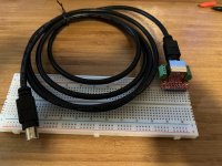
Continuity tests failed on the existing cable, but turns out they still sell Mitsubishi printer cables: https://www.amazon.com/dp/B0BB1QTF1Y
1711381341048.jpeg

Also note that the green PCB break out boards only have 6 pins since they are intended for use with RGB. But this should include the required pins (need to confirm).
 
The Neo Print manual (along with some mystery MVS carts I picked up at the same time) is being shipped out via Fed Ex. Should get to me soonish. I'll scan every page and get it into the internet archive or similar along with scans of the relevant printer manual pages.

Also finally found my stash of arduino nanos. So should be able to at least capture the TTL signal from the Neo Print this weekend (assumming I can remember how to protect the input from over voltage since I can't say for sure it will be limited to 5v from the Neo Print).
 
Last edited:
OK, I think this will apply some degree of over voltage and current protection.
1711650806848.png


But also thinking I'll cut apart the non-working mini din 8 cable and hook it up to an oscilloscope before going for the Arduino.
 
While a lot of the Neo Print cartridges are weird, I've not seen them with sockets. Would think that would prevent them fitting in the case properly (I have a bootleg MVS cart with some socketed chips, but there are cutouts in the top board for them). Wondering if that was a translation thing? Still trying to figure out the batteries in some of them.

https://www.arcade-projects.com/threads/neo-print-cartridge-batteries.28918/
Not necessarily…

I have an original Metal Slug 2 with the original Rom removed and replaced with a socket. It’s now possible to play with the original rom, or trap15’s turbo rom.
I’ve swapped them around before and in each case I can close the unmodified case back up without issue.
 
Not necessarily…

I have an original Metal Slug 2 with the original Rom removed and replaced with a socket. It’s now possible to play with the original rom, or trap15’s turbo rom.
I’ve swapped them around before and in each case I can close the unmodified case back up without issue.

I'm assuming this is on the top board? The bottom seems like it would lack the required clearance. I've got a boot leg board I made into a NeoDiagnostics cart that has sockets, but there are cutouts in the top board for EPROMs on the bottom. Only flash RAM fits otherwise.
1711655365311.jpeg
 
I'm assuming this is on the top board? The bottom seems like it would lack the required clearance. I've got a boot leg board I made into a NeoDiagnostics cart that has sockets, but there are cutouts in the top board for EPROMs on the bottom. Only flash RAM fits otherwise.
1711655365311.jpeg
Hmmm… can’t remember off the top of my head, but you’re almost certainly right.

Next time I’m with it I’ll check and let you know.
 
Can't detect anything that looks like a signal from pin 6. Feel I may be missing something. It's not looking for 3v from the printer is it?

Edit: new plan, redid the breakout board setup to give easier access to the DIN8 pins and added a 3.5mm phone jack. Between the two channels on my main oscilloscope and a crappy little aliexpress special I should be able to get a better sense if anything is happening. Just need to find the rest of my probes first...
1711829283056.jpeg
 
Last edited:
Neo Print manual should arrive tomorrow from Japan.
 
This dump maybe a bootleg , it would be nice to see another one to double check the sound roms....

There's not much documentation around, so good news you found the manual!
 
There's not much documentation around, so good news you found the manual!

Plan is to scan the manual and get a PDF online someplace. It'll be in Japanese, but there's always Google translate.
 
This dump maybe a bootleg , it would be nice to see another one to double check the sound roms....

There's not much documentation around, so good news you found the manual!

Should i unsoldered and dump the sound roms? Say the magic world! :)
 
Premature, but found a camera upgrade should everything else get resolved.
1711992189854.jpeg
 
Manual arrived and includes a sexy centerfold.

1712058705873.jpeg


Wiring diagram is interesting... it shows RGB as the display, which I've yet to see working, and it includes s-video passed back into the board from the printer. Also clearly shows here and elsewhere that both the din-8 and stereo phono jack connections to the printer are needed.

Will try to translate the trouble shooting section and will have to think about the best way to scan this in. Don't want to unbind it, so may just have to do one page at a time.
 
nice job. so this is a filter for the billboard and controls?

Looks like it's for the billboard & control panel fluorescent light. Not clear on the 12v main board connector. I think elsewhere this is documented as "flash" but it may be "fluorescent".
1712061753368.jpeg


Edit: @Mrhide think I figure it out. SSR is solid state relay. So not a filter board, but the 12v from the main board turns on the AC line to the fluorescent lights.
 
Last edited:
Huh... wiring schematic shows a TEST and SERVICE switch on the same ten pin header that the FL relay connectors are on. Thinking I'll hook things up and see what happens if I ground those pins from the error screen.
 
Trying to map the wiring diagram to the physical board. Diagram seems to list a 40+ pin "CN11" while the board has things broken out into sub groups. I think the four pin COUNT connector is where I need to find the TEST and SERVICE buttons, but there are a lot of seemingly random +12v pins in there. Going to need to check every pin and mark it as ground or vcc before I go further.
 
Back
Top