What's new
Here's a romset that will run. Burn as the files suggest.
Hi,
I have the Romset installed thank you and I'm now getting activity throughout the board where previously I was just getting a low signal on the logic probe.
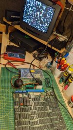
The various RAM chips are pulsing but I'm not getting any graphic output at all. I'm connecting to a TFT monitor via my GBS_control enabled GBS_8200 video converter board.
 
Last edited:
Hands Up! ?(

I think I messed up burning the ROM set.

I've since found this guide on splitting the files and using a using a TL866II Plus programmer with adapter.

Seems I need to split the files into 512kb banks. So I only need to split the second file is that correct? Then burn in three 512kb banks?

https://github.com/mafe72/27c160-tl866-adapter

Thanks...
 
Last edited:
Here's a romset that will run. Burn as the files suggest.
Hi,

Here's the ROM set installed and I'm calling this progress!
At least now I have something to work with.
I've literally only just got this installed and fired up, unfortunately I don't have any time to diagnose this tonight but this is a great start.

After checking address lines etc. my immediate target will be the RAM chips and the 3 x 74LS245's

Thanks again for the help thus far...

Any pointers gratefully accepted...
 

Attachments

  • PXL_20220317_190631047.jpg
    PXL_20220317_190631047.jpg
    253.3 KB · Views: 94
Yep now your attention on anything on the main data bus, 245's, ram etc.

245's near the jamma connector often get blown by noob's plugging it in backwards very common.
Also check the reset is working correctly, that can also make it hang like this.
 
Reset is working.

I've got all highs on the 3 x 245's pins 11-20 except U21 which has pin 16 as low. Pin 1 (DIR) on all 245's is low and pins 2-9 (a1-a8) give no reading.
 
So I removed and socketed 3 x new 245's but not difference.

On switching dip switch 6 I'm getting what I believe to be an attract tune so my repair of the sound section seems to have worked.

Graphics remain garbled and frozen but I have got the odd larger almost recognisable sprite shape?

I'm going to swap the clock oscillator for the 68000. It reads okay with my meter htz but I don't have equipment to better check it so I'll replace it with new. I don't have activity on any address or data lines from the 68000 so that would rule the clock out.
The reset signal is high and the halt signal is low. Is that what I should be reading?
Other than that it's RAM next I need to check, particularly the two large IC's adjacent to the eproms D42832C-15L?
 
Last edited:
68000 clock oscillator has been replaced with no change.

So I have 4 x T6116S45L RAM chips in the centre of the board. I'm guessing they're attached to graphic output?
All relevant pins pulsing except pins:

18 = CE Low
19 = A10 Low
20 = OE Low
21 = WE High

Are these correct readings?
Should WE be high???

I'm beginning to wonder whether the problem is the actual 68000 CPU itself.
 
Last edited:
Now I'm getting really confused!

I removed the eproms and I get exactly the same graphic output.

Thinking back I may not have been getting graphic output through the GBS_control display adapter from the start. As soon as the supergun was connected I got graphic output. Which just happened to coincided with installing the eproms.

I think I need to have a stop and think and double check if these eproms are connecting/working in the sockets correctly or do I have a none working 68000 CPU?
 
I'm beginning to wonder whether the problem is the actual 68000 CPU itself.
Maybe, if it's been running overclocked (often on those boots) they can get cooked.

Program roms may also not be set up correctly, send me a pic of the back of the PCB, there is some solder jumpers that need setup sometimes.

Also reset may not be 100% change the capacitor anyway just to be 100% sure.
 
Interesting discovery!

The 40pin eprom socket that was assumed is for a 27C400 chip seems to have a different pinout?

I'm going to continuity check and map it to see what's going on here.

Pinout reads:

1 bgack--------------- --40 vcc
2 pin 11 on 27c800-----39 vcc
3 d15--------------------38 vcc
4 d14--------------------37 a16
5 d13--------------------36 a15
6 d12--------------------35 a14
7 d11--------------------34 a13
8 d10--------------------33 a12
9 a2----------------------32 a11
10 d8--------------------31 a10
11 gnd-------------------30 gnd
12 d7--------------------29 a9
13 d6--------------------28 a8
14 d5--------------------27 a7
15 d4--------------------26 a6
16 d3--------------------25 a5
17 d2--------------------24 a4
18 d1--------------------23 a3
19 d0--------------------22 a2
20 pin 10 on 27c800----21 a1
 

Attachments

  • InkedPXL_20220321_202658274_LI.jpg
    InkedPXL_20220321_202658274_LI.jpg
    228.3 KB · Views: 67
Last edited:
Maybe, if it's been running overclocked (often on those boots) they can get cooked.

Program roms may also not be set up correctly, send me a pic of the back of the PCB, there is some solder jumpers that need setup sometimes.

Also reset may not be 100% change the capacitor anyway just to be 100% sure.
Thanks, do you mean the cap adjacent to the 68000 only I did change that for new as a matter of course...

Have a look at my recent post re that second socket, see what you think.
 
Yes, looks like you changed the reset cap.

Sockets look fine, the 27c400 goes in the smaller socket.
The jumpers i refer are on the underside (if they exist on your pcb - they should. )
 
Yes, looks like you changed the reset cap.

Sockets look fine, the 27c400 goes in the smaller socket.
The jumpers i refer are on the underside (if they exist on your pcb - they should. )
No jumpers under the board see pic.

The pinout of the smaller socket seems to almost match the 27c4096 not the 27C400?

Would that not be an awful lot of jumpers to get it to match the 27C400 pinout?
 

Attachments

  • PXL_20220321_230438351.jpg
    PXL_20220321_230438351.jpg
    216.8 KB · Views: 67
Last edited:
I've reburned the 27C800 eprom having realised I think I had the dip switch set wrong on the adapter when I burnt it initially.

I now get activity on the CPU data and address pins. It's stuck high but at least it seems there's a connection to the eprom.

So I think and hope that now its just a matter of getting the 27c400 connecting to the board correctly.
 
Last edited:
At this point, you have a different board to most of the Mstreet6 out there
The GAL (empty) socket is vertical on yours and normally horizontal with a couple of jumpers on the underside.

It's also possible they changed the layout of the lower rom to 4096

10mhz stolen for jaleco hw LOL xD
 

Attachments

  • IMAG0241[1].jpg
    IMAG0241[1].jpg
    231.7 KB · Views: 69
At this point, you have a different board to most of the Mstreet6 out there
The GAL (empty) socket is vertical on yours and normally horizontal with a couple of jumpers on the underside.

It's also possible they changed the layout of the lower rom to 4096

10mhz stolen for jaleco hw LOL xD
Oh! that's brilliant!

But very typical for me to end up with a board that's different from the norm!

I initially thought this approach would be easier but now I'm thinking maybe I should try and populate the daughterboard that I removed.

I have since adapted it's pins so it will easily go back onto the 27C800 socket so I do have both options available to me.
 
Back
Top