Thought I'd write a more comprehensive, in-depth guide for using this card emulator with Derby Owners Club so others don't struggle like I had to.
You will need the Sega Serial Conversion PCB #838-13661. I'll just call this 'Serial PCB'. This may change in the future as the protocol has been reverse engineered and so may be added to the emulator in the future.
This info MAY work for Virtual-On Force and other games that use this PCB.
Here's a picture of it.
1. Connecting to CN4 with a USB.
1a.
You will need a USB - RS232 cable, preferably one with an FTDI chip or similar. You can get pre-stripped ready-to-solder cables; I got
this one. Parts # is USB-RS232-WE-1800-BT_0.0 <--
MAKE SURE you get the one with '0.0' on the end otherwise you will be sending 3.3v/5v down the red wire (usually a ground). Use the datasheet that comes with your cable (or just make sure you know the pinouts).
1b.
Get yourself a female 9-pin serial. I brought
this as it was cheaper than a single serial port from RS/Digikey and came with a bunch of extras and some plastic shells to make it look neat.
1c.
Wire it up; takes 5 minutes with a soldering iron. If you don't have one I suppose you can use heat-shrink to keep the wires in place against the contacts.
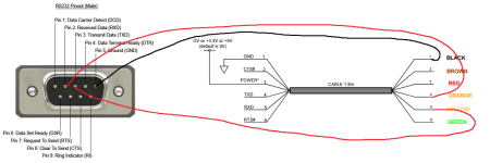
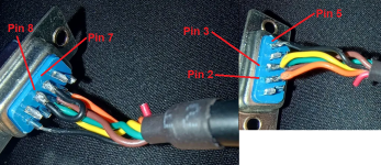
DON'T do what I did and wire transmit into transmit and receive into receive. It won't work and you'll have a massive headache trying to figure out why it won't work. This wiring diagram image ONLY applies to the cable I linked above; so again make sure you know your USB pinouts or use the datasheet for your cable to correctly apply the information here to your specific setup.
Pin 2 on Serial (Receive) - Transmit on USB
Pin 3 on Serial (Transmit) - Receive on USB
Pin 5 on Serial (Ground) - Ground on USB
Pin 7 (Request to send) & Pin 8 (Clear to send) will need to be connected with a jumper. Do this on the serial port itself, not on the USB side.
1d.
Install the FTDI VCP driver so your device recognises the USB and it appears as a virtual COM port. Obviously, install the relevant drivers if yours has a different chipset.
2. Connecting CN7 on the Serial PCB to CN8 on the Naomi.
2a.
You will need two JST-NH 6-pin connectors and pins. I used 28 AWG wire and it works fine.
The SegaRetro.org US manual for DOC is wrong. Please trust me on this.
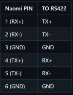
These are the pinouts, by Bobby Dilley.
Text guide:
Pin 1 on Naomi - Pin 1 on Serial PCB
Pin 2 on Naomi - Pin 2 on Serial PCB
Pin 3 on Naomi - Pin 3 on Serial PCB
Pin 4 on Naomi -
Pin 6 on Serial PCB (US Manual messed up here, as it has Pin 4 to Pin 4 which grounds the TX+.)
Pin 5 on Naomi - Pin 5 on Serial PCB
Pin 6 on Naomi -
Pin 4 on Serial PCB (US Manual messed up here, as it has Pin 6 to Pin 6 which grounds the RXD+.)
3. Powering the Serial PCB.
3a.
You will need a 4-pin and 8-pin JST-NH connector. I used 28 AWG wire and it works fine. Yes, for some reason the Serial PCB has an 8-pin for power but only uses 4 pins.
If you have a JVS Type 3 IO board you can use CN8, which is a 5v header. The IO board gets power from the CN7 header (there is a 5v header on the Naomi you can use to power it, but that's a different topic).
Pin 1 on 4-pin (5v) - Pin 1 on 8-pin
Pin 2 on 4-pin (5v) - Pin 2 on 8-pin
Pin 3 on 4-pin (Gnd) - Pin 7 on 8-pin
Pin 4 on 4-pin (Gnd) - Pin 8 on 8-pin
If you don't have a JVS IO board then you will be able to make a cable (or a split cable to power both IO & Serial PCB) coming off the 5v header on the Naomi, that will follow the same wiring scheme (the manual is actually correct for this).


 to
to 


