I don't know where/when this information can be applicable (perhaps another 32Mbit SIMM =>? conversion) but I took the time and identified the pinout of a CPS3 64 Mbit SIMM pinout. As you know, all the SIMM modules for CPS3 system has 72 pins and although they seem to be double sided, they are directly connected to their pair on the other side of the PCB, meaning there are NOT individual 144 pins...
For the reference, I took the photo of the SIMM and numbered the flash ICs.
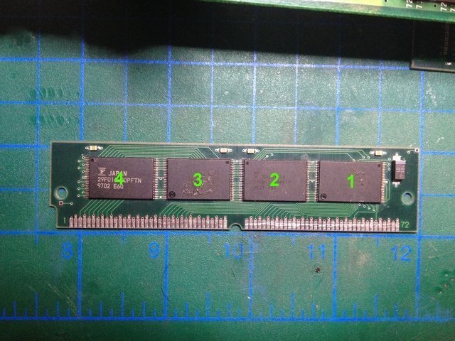
There are 2 x Normal pinout and 2 x reverse pinout Fujitsu flash ICs on a 64 Mbit SIMM module. Again they are MBM29F016-90PFTN (Normal pinout) and MBM29F016-90PFTNR (Reverse pinout)
IC1: Reverse Pinout
IC2: Normal Pinout
IC3: Reverse Pinout
IC4: Normal Pinout
There are no flash ICs or solder locations on the back side of the PCB.
Here is the pinout of the 64 Mbit SIMM PCB:
Although I double checked, there are N.C. (Not connected) pins. If you know some/all of them connected to somewhere please comment. From here, I'll move on to the 32/128Mbit module hoping, may be, with a trick or mod converting one into a 64 Mbit SIMM could be possible. But just for now, they seem to be quite different in nature, especially when you look at the common single /CE (Chip Enable) pin on 64 Mbit SIMM where 32 Mbit SIMM has 4 individual /CE pins. Anyway, I'll try to map that one as well...
For the reference, I took the photo of the SIMM and numbered the flash ICs.
There are 2 x Normal pinout and 2 x reverse pinout Fujitsu flash ICs on a 64 Mbit SIMM module. Again they are MBM29F016-90PFTN (Normal pinout) and MBM29F016-90PFTNR (Reverse pinout)
IC1: Reverse Pinout
IC2: Normal Pinout
IC3: Reverse Pinout
IC4: Normal Pinout
There are no flash ICs or solder locations on the back side of the PCB.
Here is the pinout of the 64 Mbit SIMM PCB:
| Pin | Conn. | Note |
| 1 | Vcc | Common |
| 2 | Vcc | Common |
| 3 | D7 | IC4 (Normal) |
| 4 | D6 | IC4 (Normal) |
| 5 | D5 | IC4 (Normal) |
| 6 | D4 | IC4 (Normal) |
| 7 | D3 | IC4 (Normal) |
| 8 | D2 | IC4 (Normal) |
| 9 | D1 | IC4 (Normal) |
| 10 | D0 | IC4 (Normal) |
| 11 | GND | Common |
| 12 | D7 | IC3 (Reverse) |
| 13 | D6 | IC3 (Reverse) |
| 14 | D5 | IC3 (Reverse) |
| 15 | D4 | IC3 (Reverse) |
| 16 | D3 | IC3 (Reverse) |
| 17 | D2 | IC3 (Reverse) |
| 18 | D1 | IC3 (Reverse) |
| 19 | D0 | IC3 (Reverse) |
| 20 | GND | Common |
| 21 | D7 | IC2 (Normal) |
| 22 | D6 | IC2 (Normal) |
| 23 | D5 | IC2 (Normal) |
| 24 | D4 | IC2 (Normal) |
| 25 | D3 | IC2 (Normal) |
| 26 | D2 | IC2 (Normal) |
| 27 | D1 | IC2 (Normal) |
| 28 | D0 | IC2 (Normal) |
| 29 | GND | Common |
| 30 | D7 | IC1 (Reverse) |
| 31 | D6 | IC1 (Reverse) |
| 32 | D5 | IC1 (Reverse) |
| 33 | D4 | IC1 (Reverse) |
| 34 | D3 | IC1 (Reverse) |
| 35 | D2 | IC1 (Reverse) |
| 36 | D1 | IC1 (Reverse) |
| 37 | D0 | IC1 (Reverse) |
| 38 | N.C. | |
| 39 | A20 | Common |
| 40 | A19 | Common |
| 41 | A18 | Common |
| 42 | A17 | Common |
| 43 | A16 | Common |
| 44 | A15 | Common |
| 45 | A14 | Common |
| 46 | A13 | Common |
| 47 | A12 | Common |
| 48 | A11 | Common |
| 49 | GND | Common |
| 50 | A10 | Common |
| 51 | A9 | Common |
| 52 | A8 | Common |
| 53 | A7 | Common |
| 54 | A6 | Common |
| 55 | A5 | Common |
| 56 | A4 | Common |
| 57 | A3 | Common |
| 58 | A2 | Common |
| 59 | A1 | Common |
| 60 | A0 | Common |
| 61 | GND | Common |
| 62 | /RESET | Common |
| 63 | GND | Common |
| 64 | N.C. | |
| 65 | N.C. | |
| 66 | N.C. | |
| 67 | /CE | Common |
| 68 | GND | Common |
| 69 | /WE | IC1, IC2 |
| 70 | /WE | IC3, IC4 |
| 71 | /OE | Common |
| 72 | N.C. |
Although I double checked, there are N.C. (Not connected) pins. If you know some/all of them connected to somewhere please comment. From here, I'll move on to the 32/128Mbit module hoping, may be, with a trick or mod converting one into a 64 Mbit SIMM could be possible. But just for now, they seem to be quite different in nature, especially when you look at the common single /CE (Chip Enable) pin on 64 Mbit SIMM where 32 Mbit SIMM has 4 individual /CE pins. Anyway, I'll try to map that one as well...
Last edited:
")
")
