Donkey Kong Jr.Nintendo no CLK

r67055

Enthusiast
Joined
Apr 3, 2021
Messages
309
Reaction score
86
Location
Hungary
Hello.


I would like to ask for your help with repairing a Donkey Kong Jr. PCB.

The problem is the following:
After power-on, the board displays a garbage/scrambled image (I’m attaching a picture). After a short time, the screen goes completely black.
I started checking the clock signal at the CPU. While the image is scrambled, there is also a noisy/unstable clock signal on pin 6 of the Z80. After that, the signal disappears completely.
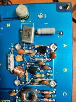
I began tracing the clock signal back from the crystal oscillator. I ran into a small issue when I noticed that the crystal is 61.44 MHz, while my oscilloscope can only measure up to 50 MHz. I still tried probing it and I can see some activity.
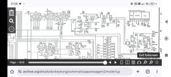
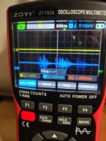
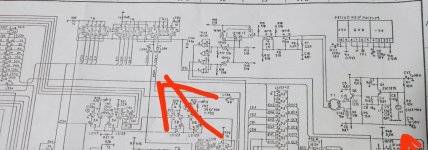
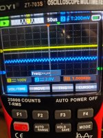
I located this section in the schematic, but I’m having trouble understanding this part of the circuit. I can see that there should be a clock signal on pin 2 of the 74LS163 IC, but I’m also seeing a strange signal there (I will attach a picture).
I’m not sure where would be the best starting point for further troubleshooting.

 

Attachments

  • IMG_20260213_182705.jpg
    IMG_20260213_182705.jpg
    121.7 KB · Views: 30
  • IMG_20260213_181551.jpg
    IMG_20260213_181551.jpg
    190 KB · Views: 29
  • Screenshot_2026-02-13-21-58-57-859_com.android.chrome.jpg
    Screenshot_2026-02-13-21-58-57-859_com.android.chrome.jpg
    114.5 KB · Views: 29
Hello.


I would like to ask for your help with repairing a Donkey Kong Jr. PCB.

The problem is the following:
After power-on, the board displays a garbage/scrambled image (I’m attaching a picture). After a short time, the screen goes completely black.
I started checking the clock signal at the CPU. While the image is scrambled, there is also a noisy/unstable clock signal on pin 6 of the Z80. After that, the signal disappears completely.
I began tracing the clock signal back from the crystal oscillator. I ran into a small issue when I noticed that the crystal is 61.44 MHz, while my oscilloscope can only measure up to 50 MHz. I still tried probing it and I can see some activity.
I located this section in the schematic, but I’m having trouble understanding this part of the circuit. I can see that there should be a clock signal on pin 2 of the 74LS163 IC, but I’m also seeing a strange signal there (I will attach a picture).
I’m not sure where would be the best starting point for further troubleshooting.
 
The -5V rail is not correct. I measure -3.8V at the JAMMA power converter. The PCB draws 0.71A. I don’t know if that current is too high, but I suspect it is.


How can I determine which component is drawing too much current?
 
It's probably better if you point to the PDF too: https://www.arcade-museum.com/manuals-videogames/D/DKJr.pdf
I would check pin 6 of the Z80 which is the input clock and see what you get there, for sure it will in the low 4-6 Mhz range.

What do you see there?

How can I determine which component is drawing too much current?
Try touching the chips and see if any gets unusually hot.
Do you actually see any activity like that screen that you showed is changing or do you hear any sounds if you insert a coin?
 
It's probably better if you point to the PDF too: https://www.arcade-museum.com/manuals-videogames/D/DKJr.pdf
I would check pin 6 of the Z80 which is the input clock and see what you get there, for sure it will in the low 4-6 Mhz range.

What do you see there?


Try touching the chips and see if any gets unusually hot.
Do you actually see any activity like that screen that you showed is changing or do you hear any sounds if you insert a coin?
The picture and the inputs are completely dead, since the clock signal is not correct.


I started measuring the current and found that two ICs (10125) were getting very hot. I removed them one by one and measured the current each time.


When I removed the first one, there was not much change — it still drew about 0.7A on the -5V rail. Then I removed the second one, and the current dropped to 0.3A. I was happy and replaced both ICs (fortunately I had spare parts with me), but the problem remains.
 
It's probably better if you point to the PDF too: https://www.arcade-museum.com/manuals-videogames/D/DKJr.pdf
I would check pin 6 of the Z80 which is the input clock and see what you get there, for sure it will in the low 4-6 Mhz range.

What do you see there?


Try touching the chips and see if any gets unusually hot.
Do you actually see any activity like that screen that you showed is changing or do you hear any sounds if you insert a coin?
Z80pin6
 

Attachments

  • 17711073721226590432280544369641.jpg
    17711073721226590432280544369641.jpg
    183.7 KB · Views: 22
The clock signal does not even reach pin 2 of the 74LS163.
 

Attachments

  • IMG_20260214_232810.jpg
    IMG_20260214_232810.jpg
    116.1 KB · Views: 21
then you should go backwards from that 74LS163 till the Crystal and see what is failing. I doubt it's a cap or resistor unless it's clearly damaged and rather a transistor or that 10136
 
then you should go backwards from that 74LS163 till the Crystal and see what is failing. I doubt it's a cap or resistor unless it's clearly damaged and rather a transistor or that 10136
There is signal on the transistors, but there is no signal at the T1 coil. There is also no signal on pins 12 and 13 of the 10116.
 
There is signal on the transistors, but there is no signal at the T1 coil. There is also no signal on pins 12 and 13 of the 10116.
I measure -1.34V on pins 12 and 13.


However, the -5V rail is still only -4.6V, which also seems suspicious to me. It still doesn’t look fully correct on the negative supply side, because if I disconnect the PCB, I measure -5.3V on the -5V rail with no load.
 
I haven't checked on this PCB, and this one is really old, but usually, the -5V are used for sound generation rather than to generate the CLK signal for the CPU, but as I said, I haven't checked in detail. Maybe some talented minds can pitch in.
@Ape Cosplay @tovar
 
A voltage of -5.1V is absolutely necessary for the ECL components.
Otherwise, the PCB will not start...........
 
A voltage of -5.1V is absolutely necessary for the ECL components.
Otherwise, the PCB will not start...........
Thank you for your reply. I suspected that something is still not right in the -5V section.


Can you suggest a way to narrow down which component might be pulling the power supply down this much? Or should I remove the components from the PCB one by one?
 
Hello,

* I understand it's an original PCB.

* The crystal is 6MHz... more than enough for your oscilloscope. No motherboard from the 80s uses a 60MHz crystal, much less one with a Z-80 CPU.

* On a PCB of that age, it's advisable to remove the ICs from the socket, including the CPU, clean the pins, and check the condition of the socket pins, which may be dirty or corroded.

* The -5V is usually used for the audio and RAM sections. Potential faults include capacitors, operational amplifiers, and RAM modules.

* One way to isolate the area of excessive current draw is to disconnect the lower PCB. If the excessive current draw persists, the problem is on the main board. If the excessive current draw disappears, the problem is on the lower PCB, most likely the RAM.

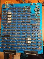
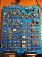
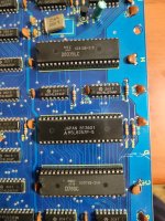
Please post photos of the PCB.
 
Hello,

* I understand it's an original PCB.

* The crystal is 6MHz... more than enough for your oscilloscope. No motherboard from the 80s uses a 60MHz crystal, much less one with a Z-80 CPU.

* On a PCB of that age, it's advisable to remove the ICs from the socket, including the CPU, clean the pins, and check the condition of the socket pins, which may be dirty or corroded.

* The -5V is usually used for the audio and RAM sections. Potential faults include capacitors, operational amplifiers, and RAM modules.

* One way to isolate the area of excessive current draw is to disconnect the lower PCB. If the excessive current draw persists, the problem is on the main board. If the excessive current draw disappears, the problem is on the lower PCB, most likely the RAM.

Please post photos of the PCB.
Hello. Thank you for your reply. I got a bit confused. I thought the 60 MHz crystal was for the CPU. Unfortunately, the PCB is not original. The 6 MHz crystal is on the upper PCB, where the CPU is located. I thought the 6 MHz crystal was for the sound section. There is still a problem on the -5V line. I will measure the voltages shortly after disconnecting the lower PCB.
 

Attachments

  • 17711573209902448676868617413722.jpg
    17711573209902448676868617413722.jpg
    354 KB · Views: 22
  • 17711573387457684380810588622383.jpg
    17711573387457684380810588622383.jpg
    159.9 KB · Views: 22
  • 17711573653628059212070209336774.jpg
    17711573653628059212070209336774.jpg
    358.5 KB · Views: 24
  • 17711573810155532622666563376816.jpg
    17711573810155532622666563376816.jpg
    249.2 KB · Views: 23
Hello. Thank you for your reply. I got a bit confused. I thought the 60 MHz crystal was for the CPU. Unfortunately, the PCB is not original. The 6 MHz crystal is on the upper PCB, where the CPU is located. I thought the 6 MHz crystal was for the sound section. There is still a problem on the -5V line. I will measure the voltages shortly after disconnecting the lower PCB.
I disconnected the lower PCB, and the measurements show the same result — the voltage still drops to -4.3V. I cannot find any signs of overheating.
 
I disconnected the lower PCB, and the measurements show the same result — the voltage still drops to -4.3V. I cannot find any signs of overheating.
Sorry, I forgot that I had powered the lower PCB separately through the edge connector, and I only unplugged the ribbon cable. So my previous measurement was incorrect.


I removed all the cables and completely isolated the lower PCB. In this case, I measured that the voltage on the upper board is exactly the same as at the power supply: -5.3V.


So it looks like the short circuit is on the lower PCB.
 
Ok, I don't remember this type of PCB very well given the time that has passed since I had it, and obviously (looking at the photo of the PCB and schematic) yes, this PCB has a 60 MHz crystal for dot clock (video synchronization), although the program CPU runs at 3 MHz.
Thanks nem!

* Also visually inspect the solder side of the PCB, checking that there are no pins rubbing against each other or deep scratches.
 
I investigated the -5V rail because the large voltage drop was bothering me.


I removed all the ceramic ICs that receive -5V. After removing each component, the supply voltage started to increase gradually. I couldn’t find any logic as to which one might be shorted.


If I remove all the ICs, I measure -5.3V.
If I insert just one IC (any of them, in random order), the voltage immediately drops to -5V and it already draws about 300mA — no matter which IC I insert. As I keep inserting more ICs, the voltage keeps dropping further.


Could my power supply be weak? It draws about 0.3A when all components are installed.
 
Back
Top