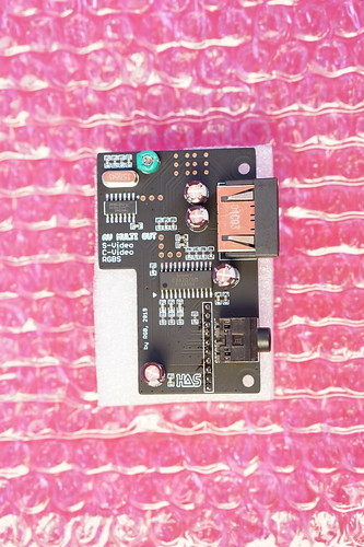
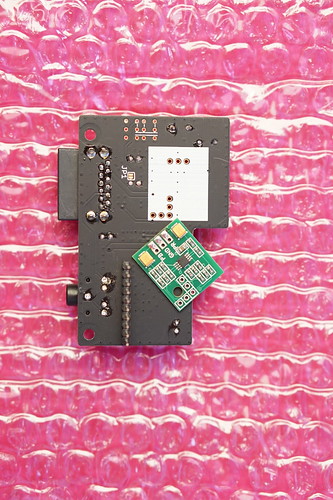
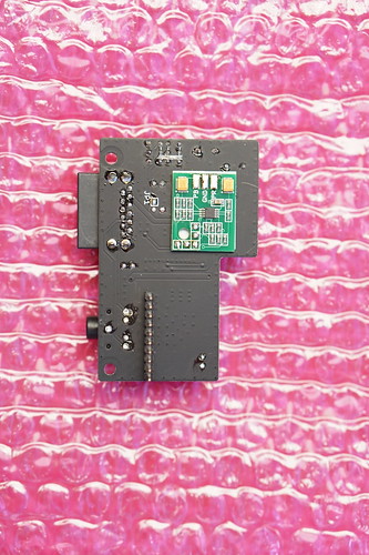
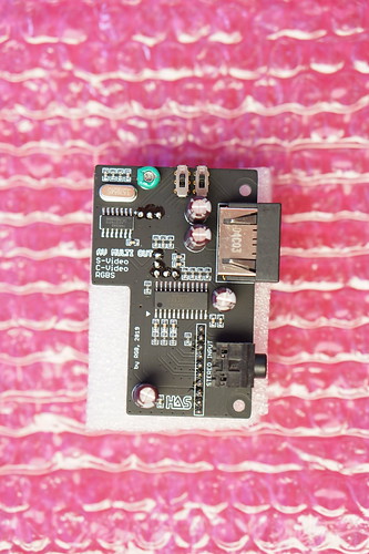
I have an MV1F. Stereo only outputs through those 4 pin headers. If you're sending the audio signal to an amplifier, use the headphone header. That mono/stereo switch controls the headers. You're only going to get mono out of the jamma connector. I think it's only the multi cartridge boards that are able to output stereo via the jamma edge since it uses a slightly different pinout. That said, making a 4pin to headphone jack connector is really easy. The best part is the audio quality is superb and has far less background noise than an AES.
Last edited: