What's new
Still working on Frank_FJS Minigun Supergun Advanced 2.5 (9 pin)

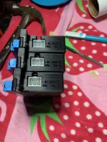
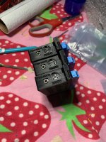
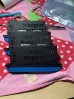
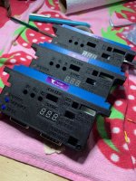
First assembly and trial fit is complete - as you can tell I'm not a profesional product protographer :) They actually look much nicer in real life than they do in these photos (that's also what my Tinder profile says). Fit is absolutely spot on and the shells look really nice with the writing embossed in - I'm extreamly pleased with the outcome.
IMG_5823.jpegIMG_5822.jpegIMG_5825.jpegIMG_5824.jpeg

I am not however extreamly pleased with the path I took to get there. I've basicly gone as far as I can go with Sketchup - it doesnt work the way I want and it still wont produce models that slice without hideous warnings. I'm going to start experimenting with Blender which will be another 40 hours of learning to gain basic skills. Tool selection is really important, I should have started with Blender in the first place.

Remember those Megadrive 2 cables that i said were cheap and plentiful? Yeah, still waiting for those so I can test functionality.
 
Still working on Frank_FJS Minigun Supergun Advanced 2.5 (9 pin)

Aliexpress came through and delivered my $5 MD2 SCART cables

If you've ever wondered why you can buy a MD2 scart cable for $5 off Ali, and Insurrection Industries want $25. This is why. The wires are the width of a human hair, the shielding is non-existent, the shell is glued closed.

But to my shock and amazement; despite being made of the cheapest materials known to man - it's all in there and it seems to all work. Correctly grounded, R, G, B lines correctly attenuated with a cap and tied to ground with a resistor.
IMG_5859.jpegIMG_5860.jpeg

My biggest concern was that cheap MS2 SCART cables dont wire the CSYNC pin at all, they rely on Composite video for their sync signal. There is actually a really good reason for this, in some territories the CSYNC pin is used for SCART signaling and carries 9v - 9v up your CSYNC hole will destroy all but the hardiest broadcast equipmment. So cheap SCART cables dont wire it. But of course the Minigun doesnt generate Composite video, ONLY SCYNC, so how to send CSYNC down pin 5?

But of course FrankFJS being the absolute legend has already solved this problem. He tied pins 5(composite) and 4(CSYNC) together on the board to solve this problem. I thought I was going to have to do this with a bodge wire. Frank if you ever read this - that was a really nice touch! I noticed it and appreciated what you had done and why you had done it.
9pin.png

So ready to start testing - I'm sorely tempted to just plug everything in without testing it and cross my fingers...
 

Attachments

  • IMG_5863.jpeg
    IMG_5863.jpeg
    225.6 KB · Views: 94
Still working on Frank_FJS Minigun Supergun Advanced 2.5 (9 pin)

Today was a good day in supergun land

I threw caution to the wind and pluged it all fired it up and it worked perfectly, first time. So I tried the other two, and they worked perfectly first time. I actually could not believe it. It was a really, really good moment.
IMG_5887.jpegIMG_5889.jpeg

I spent most of the rest of the afternoon testing all the inputs, adjusting the R, G and B levels to be nice and conservative, adjusting the voltmeter to show the correct voltage, and burning in to get rid of that "new cap hum" on the Audio line
IMG_5901.jpeg3646D7FD-2CB2-4C52-91B3-36B0F56F79BF.jpeg

I used my trusty MDR-V6 headphones. The design is from 1985 and they have never been re-engineered to cut costs. They are incredibly well made. The sticker proudly declares (edit) "For Digital". What kind of looser would want to listen to analogue audio anyway I ask you?
IMG_5890.jpeg


Key learnings from today
1) Variable Resistors (potentiometers) are not standardised from the factory, if you set them all to "the middle" thats not necessarily the middle of their resistance range. In this case the pots are controling the R G abd B gain, too high could potentially damage video equipment. Every single one needs to be level-set by hand after assembly which is extremely labor intensive - lots of electronic devices have pots buried in the strangest places, does someone manually set every single one of these?
2) The variable resistors on the minigun are counter-intuituve, turning the pot left (anti-clockwise) turns the levels UP, turning the pot right (clockwise) turns it DOWN
3) New capacators in the audio section sometimes produce a hiss on the audio line (one was perfect right out of the box, one took about 2 hours to cook out, the other is still cooking 10 hours later), Again this is massively labor intensive - I wonder how they do this in a factory?
4) I needed test equipment to test my test equipment; calibrating the voltmeter on the minigun meant measuring the voltage with the multimeter, but in order to trust the reading on the multimeter I had to valudate it with the Oscilloscope. Luckily they matched, otherwise I would have needed test equipment to test my test equipment to test my test equipment - turtles all the way down...

Today was a good day in Supergun land
 
Excellent work on those cases! I also did a from scratch design for the minigun and went through a similar amount of test prints.
If you want to swtich your 3d modelling software, have a look at Fusion 360. I do all my models with it and it is free to use for private projects.
 
Excellent work on those cases! I also did a from scratch design for the minigun and went through a similar amount of test prints.
If you want to swtich your 3d modelling software, have a look at Fusion 360. I do all my models with it and it is free to use for private projects.
Thankyou for this - initally I was attracted to blender because of the free open source nature of the software. But Fusion 360 is clearly the better tool for the kinds of jobs that i want to do. Thanks!
 
Still working on Frank_FJS Minigun Supergun Advanced 2.5 (9 pin)

Nearly done with these. Just got a little bit of testing to go. I specifically want make sure that it is safe for modern equipment. Scope is an HP54600A which is great for this sort of thing, but would be even more great if it were 4 channel...
IMG_5970.jpeg

There are three key areas I want to test
1) RGB voltage = 2-5 volts at the JAMMA edge - needs to be .7v for modern equipment
1b) Can we move this out of spec by dialing the level pots all the way up?
2) Sync Voltage = 2-5ish volts at the JAMMA edge - needs to be .7v for modern equipemnt that expects 75Ohm
2a) Does the TTL jumper work as expected and send the full 2-5v?
3) Audio voltage = ??? at the JAMMA edge - needs to be under 3.3v for consumer equipment

So that was the plan - but instead I got distracted looking at how Chun-Li looks on an oscilloscope in composite video. I feel like Cypher from the Matrix - I'll hit the testing later
IMG_5953.jpeg
 
Still working on Frank_FJS Minigun Supergun Advanced 2.5 (9 pin)

Lots of voltage testing today - this was harder than I thought because to get an accurate reading the signal needs to be terminated. On consumer equipment this means it needs to be pluged in. Which would be fine, but some of the things I was testing were "can I get 5v pp out of the sync line if i set the sync jumper to TTL". The solution was to RGB mod a TV that I bought from a local auction site for $1 so when it inevitably blows up nothing of value will be lost.

IMG_6030.jpeg IMG_6025.jpeg

So my tests were as follows

1) RGB voltage = 2-5 volts at the JAMMA edge - needs to be .7v for modern equipment
1b) Can we move this out of spec by dialing the level pots all the way up?

This does NOT work as expected. if you crank those level pots all the way to the left you can get the full 5 volts coming out. You need to dial them in, by hand, with an oscilloscope to make them safe - I had to set every single level, on all three of the superguns, to .7 vpp by hand.
My cheap kerb pickup TV complained bitterly when I sent it 5v or Red, but it didnt actually die - top engineering sony! OSSC owners would not be so lucky
I'll probably post this over on the main Minigun thread later - but if these level are set wrong, or (more likely) have never been set at all, then these devices are NOT safe for modern equipment. This was a big surprise...
IMG_6044.jpegIMG_6033.jpegIMG_6032.jpeg

2) Sync Voltage = 2-5ish volts at the JAMMA edge - needs to be .7v for modern equipemnt that expects 75Ohm
2a) Does the TTL jumper work as expected and send the full 2-5v?

This works as expected.
When the sync jumper is set to "75 Ohm" then CSYNC is sent at approx .6v.
When it's set to "TTL" then CSYNC is sent at approx 4v
My cheap kerb pickup TV complained bitterly when I sent it 4v of sync, but it didnt actually die - top engineering sony! OSSC owners would not be so lucky
IMG_6048.jpegIMG_6046.jpeg

3) Audio voltage = ??? at the JAMMA edge - needs to be under 3.3v for consumer equipment
I couldnt test this because the sound test on NeoGeo is absolute rubbish - I'll be using a capcom CPS2 board for this testing. Stay tuned for tomorrows episode
IMG_6050.jpeg
 

Attachments

  • IMG_6049.jpeg
    IMG_6049.jpeg
    238.9 KB · Views: 77
  • IMG_6021.jpeg
    IMG_6021.jpeg
    150.8 KB · Views: 74
Still working on Frank_FJS Minigun Supergun Advanced 2.5 (9 pin)

All the testing is finished now, I’m nearly ready to call this one “Done”

I wanted to test that the audio voltage coming out of the mini-din audio was at Ref level for consumer gear (0dBV = 1.4v = 2.8vpp) and if the voltage coming out of the headphone Jack was at line level for consumer gear (-10dBV = .45= .9vpp

I thought this was going to be really hard to test, because to do an accurate test you need an audio source that plays a single continuous tone at maximum volume

The maximum volume was easy - the CPS2 test menu was happy to
1483A5BD-DFF0-4237-9011-46C6A167D698.jpeg

But what about a single continuous tone?

of course this is trivial with a storage oscilloscope, I just played through ALL the music samples and the scope captured the whole lot.

then I could use the cursors to measure the maximum vpp across everything which was 2.5vpp. This is just under 2.8vpp which is our safe ref level for consumer speakers (0dBV)
6B59CF5C-02B1-4831-B224-1528B79E6833.jpeg

Same story out of the headphone Jack, .8vpp captured which is just under .9vpp which is our expected line level for consumer headphones (-10dBV)

So the audio section was really nice. This is the first time I’ve seen an oscilloscope test something that would (as far as I can tell) be impossible to measure any other way.

All of the testing is done, everything works as designed :)
 
Still working on Frank_FJS Minigun Supergun Advanced 2.5 (9 pin)

The Minigun is now "done" and I've started work on the power.

In order for this to be fully compatible it's going to need +5v + 12v -5v - this is common in (OLD) ATS power supplies, and arcade power supplies from 30 years ago, but not so much today. I guess skipping the -5v would not be the end of the world. But in case you havent noticed i'm not doing this the easy (or cheap) way.

Meanwell make the only power supplies i trust, and their "RT-XXA" series do indeed produce +5v, +12v and -5v in a slim and delightful looking package
https://www.meanwell.com/productPdf.aspx?i=488

The RT-65A, RT85A or RT125A would be fine. 65 watt feels a bit light, and the 85 was out of stock, so I got the 125.
IMG_6403.jpeg

Those bare terminals on the front will never do - Luckily the awesome Printmaker had produced a nice shell here
https://www.thingiverse.com/thing:3959499

There were a few things I did not like about printmakers design so I set about making one tiny change....

And made one tiny change and a large number of other changes too - now it looks like this
Revised power housing.png
I'm not super happy with the position of the "DC out" words here, they really need to be a few mm to the left to be centred properly - maybe I fix that in rev 2.

There are a couple of other bits to complete the power supply
Molex Jr female panel housing and male pins - I know this is weird, but its the molex way
Molex Jr Male cable housing and female pins - again, seems arse backward to me, but thats what the molex design guide says
Fork connectors - the "blue" ones seem to be reasonably standard size with OD of 5.7mm which fits into the meanwell power supply terminal block nicely. The "red" ones would fit too, but a lot of those arent rated for much current. The "yellow" ones are too big
20AWG wire for the cable to the minigun. FrankFJS is a fan of 18AWG for this, but even 20AWG is over spec for a little power supply like this. and I've got lots of it
16AWG wire for inside the shell. This is stupidly over-spec for this application, but I've got lots of it spare
A IEC320 C14 socket (switched with fuse) - i'm not a big fan of Aliexpress for mains powered... anything - so I'll check this guy carefully when it arrives before I decide if I can use it
https://www.aliexpress.com/item/1005002516320900.html

It's currently 1 degree outside, and the 3D printer is in the un-insulated shed, so its 1 degree inside too. I'll bring the printer inside overnight and see if I can thaw it out enough to print that shell tomorrow.
 
3D printed covers for power supplies are so handy. Safer, cleaner looking, and with a switch integrated? What's not to love?

IMG_3126.jpg
 
Yes! Exactly like that, your one looks super sweet with the 5v adjustment on the front too. Nice!
 
I printed this on an Creality ender 3 Pro, Sliced on Cura 4.10.0, Generic PLA 200/60 .2 layer height, 5 walls, 20% infill, brim for suppor Took around 10 hours.

Test print went really well, need to adjust the size of the labels on the left and right hand sides. I also want to move the 5v adjustment pot to the front and fix the indicator LED like I did on the Minigun case - at the moment it's just a big hole in the case, that wont do at all.

As you can see I tried to step up my product-photography game. I was not successful, they look like what they are which is the thing on a white sheet of paper.
IMG_6407.jpegIMG_6406.jpegIMG_6408.jpeg

I sliced this with the new version of Cura with the "brim" setting on - this totally messes up the writing that I want to put on the front (resting on the bed). I suspect this is because the brim fills up the negative space where the writing would be. I guess I could just sand down the .2mm of the brim to reveal the writing, but where would be the fun in that?
IMG_6409.jpeg

The trimpot is a "102" which is 1kohm, so ive ordered a 1khom variable resistor
And the fused switched C13 socket is still on order too

Once again... waiting on parts

I'll make all the changes and print
 
Still working on Frank_FJS Minigun Supergun Advanced 2.5 (9 pin)

The Minigun is now "done" and I've started work on the power.

I'm working on the internal wiring now - all of the parts for this are genuine molex from a reputable supplier (Digikey). The difference between a 20 cent genuine pin and a .02 cent aliexpress pin is night and day. They crimp absolutely perfectly every single time. Love it. You can also get a 50 cent molex pin that is solid instead of pressed, it's like it's been machined? Way to intricate to have been extruded. I have no idea how they can make these for 50 cents...

New Zealand (where I live) has an appalling case of "small man syndrome" - Kiwis can never just take what works and do that, nooooo, everything has to be invented (badly) here. So we dont use AWG in NZ and we dont use standard sizes. You need to measure everything. FML
IMG_6432.jpegIMG_6431.jpegIMG_6430.jpegIMG_6433.jpeg

For the internal wiring I'm using 1.5mm diameter core wire which is approx AWG14.5 - this is hopelessly over spec for the application but I have tonnes of it
PVC is mechanically tougher and doesnt get "grubby"
Silicone is more fireproof and more flexiable
I'm using PVC becasue I have lots - there is no real color standard for this so I'll be use the ATX standard
Red = +5v
Yellow = +12v
Blue = -5v
Black = COM
The spade/fork crimp connectors are new old stock that I've had sitting in my parts box for 25 years - before everything was made in china so I'm happy with the quality there

Shoe-horning the completed harness into the shell was harder than I thought because of the whole PVC/Silicone thing - 14AWG PVC wire really does not like tight bends... I might re-make the harness with silicone wire later, then I could make a smaller shell. I still havent fitted the C13 socket or moved the +5v trimpot so that might not be practical, will test fit all the rest of the parts when they arrive
IMG_6429.jpeg

in tomorrows episode... waiting for more parts!
 

Attachments

  • IMG_6424 (1).jpeg
    IMG_6424 (1).jpeg
    187.5 KB · Views: 79
Experiments in materials science, I've been trying to find the best way to "color in" the letters that I cut into the shapes.

Pretty pleased with the way these came out

This was acrylic paint that I let dry then sanded - looks nice, needs to happen in 2 stages approx 8 hours appart, is labour intensive, changes the surface of the print.
IMG_6446.jpeg

This was nail polish that I filled the letters with then cleaned up with acetone - looks really nice, can be done in one stage, takes bugger all time, does not change the surface ot the print (this would obviously not work on ABS)
IMG_6444.jpeg

I'll start experimenting tomorrow with the massive horde of minigun case prototypes that i made on the journey to final (this pile is less than 1/4)
IMG_5499.jpeg
 
Parts arrived and I was able to do the 1st test fitting for the power supply case.

it actually looks good enough, the sensible thing to do would be to stop now. But there is nothing sensible about this hobby!
C508E9DF-0BC6-4DFD-A86E-793AB425AE62.jpeg

Unfortunately the 15.5 AWG PVC wire that I was hoping to use is too stiff for this application, and too thick anyway. I’ll use 18AWG silicone instead like I should have in the first place
927BBEFF-9A88-4660-AB5D-8989935BF36A.jpeg

in order to fit the big potentiometer onto the front I’m going to have to move the power socket to the other side, move the molex connector, re-arrange all of internal support structures and design some cable management. At this point it’s going to be faster to design a whole new case rather than keep working on this one. I want to add some feet and other stuff anyway…
 
Still working on the power supply.

Unfortunately I wasnt able to modify the thingverse power supply cover the way I wanted, it turned out to be easier to steal all the dimnesionsand redraw it from scratch (thanks Printmaker! I'd like to submit my work as a remix - even tho it's technically a new drawing - but your settings wont let me)
So this is V2 of the power supply cover. I've changed a bunch of things for electrical safety. Although it's difficult to argue that an open frame power supply is "safe". I have at least made sure it's not "even less safe".

There was a really cool human factors design study here
https://www.arcade-projects.com/threads/minigun-supergun-an-open-source-supergun.9408/page-77
That I was able to take a lot of lessons from (and also help solve the problem). It's very easy to wire these up wrong and documentation is tricky. Unfortunately a new member blew up a CPS2 A board with untested supergun gear off eBay. This reflects badly on all of us, It's easily avoidable with good design

So with my human factors case study in what not to do
Pot is now on the front
AC in is now on the left side
Pinout is now labled on the front of the power supply case AND the supergun case
Power cables are keyed and can only go in the right way
dangerous screw holes are gone and fastening from the bottom,
all the internal cabling has been changed so it fits nicely.
Power supply cover.png
Will it print? Will it fit? I'll tell you in 10 hours
 
Made some power supply cables today

This was 3mm expandable cable sheath, and 5mm pre-glued heat shrink.
The housings and pins are genuine molex parts from digikey - they really are so much nicer than the chinese ones, much easier to make things with, they actually have an insertion rating, and they crimp perfectly every time. This is a "safety critical" part so not the right place to cut corners.
I used PVC jacketed wire for this, it's less heat resistant than silicone but much more resistant to mechanical stress, since this cable is going to be lying on the bench and get the crap beaten out of it mechanical stress is the most important design consideration.

I've used the closest thing that there is top a power color standard for this - although becasue these cables are straight-through and finished on both ends it doesnt really matter, but its just as easy to do it right, so why not?
Red = +5
Yellow = +12
Blue = -5
Black = GND

The Molex female pins are rated 14-22AWG, i'm using 18AWG. Because of this the "wings" dont crimp perfectly, 18AWG is not fat enough. To prevent an ugly crimp I manually trimmed the wings by about .5mm so they tuck in nicely. Who will notice? no-one ever, but it makes me feel good
IMG_6699.jpegIMG_6702.jpeg

I also wanted the wires to line up nicely where it joined the heat-shrink - so i used these zip-ties to hold everything in place while I was making the cable and heat-shrinking the ends. Once it's shrunk and the glue has set you can cut the zip ties off and the wires look nice and straight
IMG_6697.jpegIMG_6698.jpeg

The flex sheathingis bloody miserable stuff to work with - I got 3mm expandable because I wanted it to be firm to touch and 6 x 18AWG wires only barely fit. Took me ages to feed it through until I discovered the "scrunch and bunch" technique. Hard to describe but the 3mm expandable sheath can expand to more like 9mm if you force it together, feed all the wires through, then pull it back out to tighten it up.
The ends of flex-sheathing always look like untidy p*bic hair. Hang your heads in shame ebay sellers!

the solution to this is pre-glued heat-shrink. The glue is heat activated so when it is heated it locks in all those loose ends so they dont come out again - Taking a bit of extra time to ensure that the heat shrink is cut square makes a big difference to the final look too.

IMG_6696.jpeg

Here is the finished article in 1, 2 and 3 ft lengths - these take about an hour each to make - this is an idiotic waste of time and money - but every time I touch them I will know that they are perfect
IMG_6704.jpegIMG_6706.jpeg

Feels like I'm getting close to done on the power - fingers crossed that the 10 print of the front shell comes out nicely...
 
Print #2 for the power supply came out really well

IMG_6726.jpeg

This was on a Creality ender 3pro - generic PLA, .2mm height, bottom height = 1mm, top/bottom speed 15mm/sec, skirt not brim, bed = 65, filament = 200

I jammed the print head all the way down against the bed to really smear that first layer in hard - this trick works really well for PLA, is a disaster to TPU/ABS...

The trick to getting those words on the bottom face cut in really nicely is to set the bottom speed really slow (15mm) and to set the bottom thickenss to match the depth of the letters (1mm)

I'll test fit this one to make sure everything lines up nicely, then do one more print with a smaller layer height for quality, then the power supply will be done too.

Feels like my 3D modeling and printing skills are improving, the same process for the Minigun case took probably 30 prints, this one shoule be done in 3, and this one was a much more complicated job
 
Did some mechanical safety testing today - the mains power input is held in place by friction and by 4 clip tabs that grip a suitably sized tab retaining clips inside the case

I wanted to test if the power connector could pop out by accident.

No; no it cannot pop out by accident. It also cannot pop out on purpose. Removing the power socket after it is installed is not possible without destroying both the case and the socket.

I had to drill 4 holes, then rip all four tab clips out with pliers to extract.
IMG_6902.jpegIMG_6903.jpeg

So I'm highly satisfied that these are mechanically safe - This also means that I can simplify the BOM, no need for spade connectors if this part can never be removed - I can solder directly to the tabs

Now I have an excuse to print the final revision of the case with the power socket flipped over so the switch is at the front, better retention for the (now hidden) nuts, a tidy up of the writing to make it all pretty, and a bunch of other little tweaks

revised again.png

Tomorrow I'll print the (hopefully) final case, move the pot to the front, and then assemble and call the power supply "finished"
 
Back
Top