DARKSOFT LCD troubleshooting / repairs

Hello! I've got a bit of an issue with my LCD.

While removing the connector to prepare it for installation in a Jasen's CPS2 case it seems one of the pins brought along their parts-side pad (the middle pin closest to the board edge, see photo).

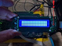
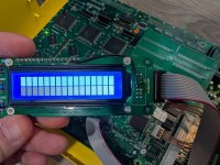
The LCD now only produces solid blocks as shown in the image, and the system outputs a green screen. :unsure:

I was hoping I might be able to do a simple bodge job on this, and was seeking to know where the indicated parts-side pad goes (to effect the repair)?
 

Attachments

  • LCD Screen Weirdness.jpg
    LCD Screen Weirdness.jpg
    152.6 KB · Views: 94
Last edited:
Thanks! I was able to use the image to pop on a quick bodge wire!

Having said that, it seems to have had little- if any- impact. The screen still exhibits weirdness. Unfortunately, I haven't a clue as to what the issue is at this point. Like before, the LCD displays blocks and the unit boots to green screen.

?(

Any advice I as to where to look next?
 

Attachments

  • stillWeird.jpg
    stillWeird.jpg
    81.9 KB · Views: 96
Thanks! I was able to use the image to pop on a quick bodge wire!

Having said that, it seems to have had little- if any- impact. The screen still exhibits weirdness. Unfortunately, I haven't a clue as to what the issue is at this point. Like before, the LCD displays blocks and the unit boots to green screen.

?(

Any advice I as to where to look next?
If it is indeed the display you can replace it with another 1602 lcd. They’re pretty cheap on Amazon. If you go back a few pages I also have a 1602 OLED from AliExpress that works.
 
Unfortunately, I'm unaware if it's the LCD specifically. Manipulating the buttons to try and flash a game in the background did not yield any LED activity on the board, indicating both the screen and controls are dysfunctional. I don't have enough knowledge to understand the issue.

I ordered a new LCD module of the same standard from eBay and will test that (since they're cheap, anyways).

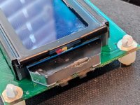
Since it may be relevant, I want to reiterate that this LCD (and module as a whole) functioned fine prior to me removing the connector (as previously mentioned). I did notice I seem to have tapped the trapezoid on the side of the LCD with the desoldering gun while I was working. I've uploaded a photo; the mark on left is rosin flux residue from my fingers; but the mark to the center-right is heat damage from the incident. Surely that couldn't have done it in, though? The damage looks minor, but inexperience keeps me from feeling confident.
 

Attachments

  • lcdWhoops.jpg
    lcdWhoops.jpg
    78.2 KB · Views: 90
Last edited:
Hello again!

I'm following up - it seems the LCD is not the root issue.

To start, let me reiterate the work done so far:
- Multi installed.
- Multi tested to verify functionality.
- LCD removed
- LCD connector removed to support installation of 90 degree joint
- LCD reconnected
- Unit fails to boot, LCD appears dysfunctional (two solid rows of blocks).

With that in mind, I ordered a new LCD unit. It arrived today. I installed the new LCD unit which is the same as the one that was removed as far as I can tell.

After powering on, I observed the top row was white blocks (the bottom row was nothing).

I then attempted to adjust the contrast using the knob on the multi-board, it was shortly after this that the unit began emitting white smoke from the location of the contrast pot, and I immediately shut down power (supplied by a known good RT-85A running 5V at the edge verified).

I don't know what to do at this point. The only thing I've changed is swapping out the connector and that's fairly simple work. I don't know what's causing the main unit to emit smoke and I didn't see anything visibly go up. The contrast pot appeared to emit white smoke a second or so after I manipulated its position.
 
Is the orientation of the connector and cable right? Sounds like power went somewhere it shouldn’t. Smoke isn’t a good sign. Perhaps check with other people who have done that mod for the case?
 
:|

I don't know how I didn't realize my orientation on that was going to be wrong no matter what. Thank you for pointing that out. I feel very silly, but it happens. In any event, popping the pins back over to the front side has- in fact- resolved the issue. I tested a few games at random, and they loaded appropriately and responded as expected to input! The white smoke was alarming, but I'm going to assume- for now- that I managed to power down before anything bad could kick off (since everything appears to be working).

A big thank you to @djsheep for helping me see the problem right in front of me.
 
Last edited:
Luckily for you the multi has several security measures in place to avoid a shortcut frying the whole pcb. Looks like you were lucky as well and noticed that quick. Enjoy.
 
Indeed! And now we know they're at least robust enough to resist a dummy who flopped a connector around without considering the orientation of the ribbon cable in his head. :D

Thanks to everyone who chipped in to help, I appreciate all the helpful comments and troubleshooting.
 
On @TodoRojo pic the connector is soldered to the top of the board (parts side) On your photos it looks like you’ve soldered to the underside (solder side). That would be the issue I reckon… hopefully no permanent damage has been done to the multi or your donor.

1742021592290.jpeg
Good catch, I can’t believe I didn’t notice that! Glad it’s working @dillingerradio
 
How did people manage to desolder the old lcd from the board? Did you just use an electric desoldering iron gun? I don’t think I’m able to get the solder off clean enough to remove the lcd screen.
 
How did people manage to desolder the old lcd from the board? Did you just use an electric desoldering iron gun? I don’t think I’m able to get the solder off clean enough to remove the lcd screen.

Hiya!

It's been a hot minute so I don't remember exactly but I'll try and recall the process (someone here can probably chime in with corrections if they spot issues):
  1. I bought a new LCD module: "1602 BLUE LCD 16x2 HD44780 with IIC I2C Serial Interface Adapter Module Display"
  2. The module came with a controller already on it, which I then removed so it matched up with the original.
  3. To remove the original, I desoldered the 16 pins from their corresponding places on the bottom of the unit (the ones which you can see at the top left of the module). I then clipped the plastic spacers, and pulled it free. In the process, I damaged the base PCB by pulling up one of the pads, because I failed to properly and fully desolder it before forcing the unit free.
  4. I seated the new module in its place, and soldered as normal.
  5. I then soldered in a bodge wire to connect a pad I damaged in the process to its respective spot on the board.

For desoldering in general, I use a Hakko FR-301 desoldering tool when space permits. For tighter spaces, a bit of braided copper wick. When solder is cemented in and just not pulling up I'll flow in some fresh stuff on top, and that sometimes helps ease the old stuff out. In situations where particularly stubborn solder has blocked a pad, but there is no corresponding part on the pad, I'll sometimes use a pin drill with a bit just slightly smaller than the pad. But this tends to be a last resort for me, since it can result in damage to the pad if done incorrectly.

In the case of my unit, inexperience lead to damaging the base PCB that the LCD module was attached to. I should have spent more time properly desoldering the pins from the bottom to ensure they would pull up freely. From what I recall, the solder on the pins on the board was a little stubborn, and rather than taking my time to fully clean the one or two pads that were stuck, I got frustrated and decided to YOLO it out (resulting in the pulled pad).

Now that I've got the part in hand again and am looking at it, though, I wonder if I couldn't have simply desoldered it from the top and lifted it free without the pins- sparing myself much of the headache. If I were doing it again, I'd probably do that instead :facepalm: :D

TL;DR:
See the 16 pads on the top left of the LCD module? Desolder those (using a desoldering gun or copper wick, or whatever method works for you). Remove the plastic spacers- I cut them since I had replacements handy, but they can be removed without the need for that if you like. Lift the module free of the pins. Put the new module in its place and solder.

 
Last edited:
Back
Top