You are using an out of date browser. It may not display this or other websites correctly.
You should upgrade or use an alternative browser.
You should upgrade or use an alternative browser.
- Thread starter JSN_
- Start date
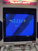
Test after reflow… seems back to square 1. I will try to tinker mister config because I think i added some dumb wallpaper script.
View: https://youtube.com/shorts/K1T_-B01kGk?feature=share
GeekMan1222
Grand Master
Im feeling charitable about this thread.
I grabbed one of my parts MS2930's to look at
First off Flyback really has nothing to do with colors if you had issues with the FBT or HV regulation you would definitely know the Flyback has more to do with voltages and the screen and working in conjunction with the HOT. None of this is a problem you are experiencing.
--------------------
Heres something else you can try if you wanted. The 3 color drive transistors on you neck board you can desolder the blue color drive transistor and put it in place of one of the other colors drive transistors and see if anything changes.
CN302 is your RGB signals coming from the video amp on the main chassis into the neck board. The pin out of these are printed on the main chassis at CN102
Reseat or even reflow CN302 neck board and even CN102 (chassis side)
If we trace the blue signal wire on the neckboards circuit we end up going through a resistor R320 and then into a transistor Q321 and finally the drive transistor Q322. This block if you will is for blue colors output into the neck of the CRT tube.
Take a pencil or something and mark the face of Q322 you could even draw a B on it or something as that is your known working drive transistor.
Take that known working transistor for blue and swap the transistor with the transistor of either Q312 (Green) or Q320 (Red)
Pay close attention to the orientation of this transistor its important the legs are in the right spots.
( Edit: infact you could even change/swap the smaller transistor Q321 with one of the other transistors of the same kind for other colors too.)
If the blue changes to either one of those other colors well you just ruled out that your Green and Red drive transistors are likely burnt up or bad.
If you still get blue and not the other colors then you know that the drive transistors are good and its something else now.
This is something fairly easy we can do to get more clues and rule things out.
So if we ruled out the drive transistors and they are all good, then what?
Well there is support passive components in the chain of the red and green signals leaving the amplifier you may want to take some time out of your day and test these. It could be resistors or capacitors. There is also a some kind of supporting transistor on the neck board before the color drive transistors but idk if that would be likely or not. If you have the means to somehow test these it may be advisable to do so.
The video amp U201 (M51387P) may actual be the problem too. I have fixed a chassis with multiple missing colors and it ended up being the video amplifier.
The video amplifer takes your RGB inputs and amplifies them for use with the outputs/drives.
Reflow the solder on this IC and test or replace the capacitors around this IC as well. Inspect the traces around this IC as well if the chassis has been recapped especially.
I know I am spitting alot of info out here but aside from your self another member may find this to be really useful info.
I wish you the best of luck
Edit:
And it is also still possible that some components ahead of the drive output transistors for Red and Green is also bad so you cannot 100% fully rule these out unless you also test these or have a way to swap and compare. Doing the above will provide more info though and is something to definitely test.
Last edited:
Thank you for the detailed post (again) @GeekMan1222 you may be feeling charitable because I bought the cab from you. 
As I said before it was working before i took everything apart and cleaned it so I really don’t know where to go.
I think I’m capable of doing a transistor swap like you said, but my overall electronics skills are being humbled when I talk to you all on here.
At this point I’m wondering if I should send the chassis and neckboard out to someone for service… do you offer that or should I reach out elsewhere?
GeekMan1222
Grand Master
Oh this is something we sold you? Forgive me its hard to keep track with all the names and usernames sometimes haha.
I'll DM you about this I am welcome to take a look at it for you if you wanted before sending it to service person like Sharp or PNL etc if it comes down to it.
I have a video tester I can substitute/inject color signals with so I can check test some things.
I'll DM you about this I am welcome to take a look at it for you if you wanted before sending it to service person like Sharp or PNL etc if it comes down to it.
I have a video tester I can substitute/inject color signals with so I can check test some things.
PM received. Thanks again! A+ service
One final thought for the group then I will be quiet for a while:
I did notice when I pushed the degaussing button that i did see some waves of red and green. Just wondering if this has any bearing as to the health of the guns or whatnot… thanks everyone for your help!
One final thought for the group then I will be quiet for a while:
I did notice when I pushed the degaussing button that i did see some waves of red and green. Just wondering if this has any bearing as to the health of the guns or whatnot… thanks everyone for your help!
advans14
Professional
Answer is no on health of guns. You can use a rejuvenator aka tube tester to test the true health of each gun.PM received. Thanks again! A+ service
One final thought for the group then I will be quiet for a while:
I did notice when I pushed the degaussing button that i did see some waves of red and green. Just wondering if this has any bearing as to the health of the guns or whatnot… thanks everyone for your help!
Prob in regards to my post and i know as i stated. But often times these games come with jacked up screen controls and there is no need for it. Once the color issue is resolved it needs to be turned down regardless to look worth a shit.First off Flyback really has nothing to do with colors if you had issues with the FBT or HV regulation you would definitely know the Flyback has more to do with voltages and the screen and working in conjunction with the HOT. None of this is a problem you are experiencing.
GeekMan1222
Grand Master
exactly I was just clarifying its not related to color issues incase anyone got confused, you shouldnt have retrace lines in your final image so its already much too highAnswer is no on health of guns. You can use a rejuvenator aka tube tester to test the true health of each gun.
Prob in regards to my post and i know as i stated. But often times these games come with jacked up screen controls and there is no need for it. Once the color issue is resolved it needs to be turned down regardless to look worth a shit.
Your dad give you that meter? Because you probably have a nicer one than a lot of us here, so that's a good start.I think I’m capable of doing a transistor swap like you said, but my overall electronics skills are being humbled when I talk to you all on here.
")
We all start somewhere with this stuff, and you just learn bit by bit. I can recap a chassis, adjust convergence, diagnose basic issues like cold solder joints etc. And then when things go off the deep end I'm here asking questions like anyone else because CRTs get mysterious and black magical. Before I owned cabs I couldn't do any of that. You learn by doing it.
Haha he certainly did. He’s retired now soYour dad give you that meter? Because you probably have a nicer one than a lot of us here, so that's a good start.
We all start somewhere with this stuff, and you just learn bit by bit. I can recap a chassis, adjust convergence, diagnose basic issues like cold solder joints etc. And then when things go off the deep end I'm here asking questions like anyone else because CRTs get mysterious and black magical. Before I owned cabs I couldn't do any of that. You learn by doing it.
I got a present.
I agree with you, it’s really cool to learn this stuff. Sometimes I get overwhelmed and think I’ll never be able to do something and then a few hours later I’m doing the thing.
I’m super comfortable modding consoles but yea these crts are a different beast.
Hey not sure if this helps but I have a ms2931 that had the same issue with a blue screen and then shutting off.
I swapped the neck board and it works fine.
I'm still trying to get to the bottom of the issue, not sure how similiar the neck boards are.
I swapped the neck board and it works fine.
I'm still trying to get to the bottom of the issue, not sure how similiar the neck boards are.
Attachments
Shouldnt be too hard. Start metering each part.
Please explain this to me like I’m 5. You are referencing geekman’s recent post about transistors?
advans14
Professional
resistors. on the neck board. Stripe colors on the resistor body = the value look up a calculator guide online. These are an unlikely fail unless you see any burnt components. Usually the flame resistors fat high wattage ones fail. If you get a reading of open or “ol” it is toast generally. Sometimes you need to pull a leg up off board in this case to double verify.
Transistors. Look up the type on the neckboard. Find out if its an NPN or PNP transistor. Put your meter in diode mode and measure the legs. Transistors have a high failure rate. If you get a suspect result of it. Desolder the whole transistor and measure on your desk. I like to put the negative lead on a PNP’s base and use the positive lead to measure the collector and emitter. It should read as a diode like -.450-.600 and below or so on each leg (depends on the specs). then swap the meter lead to be positive on base negative on collector or emitter for NPN. You can then reverse the process for both and it shouldnt be the same either way. Also there is a third test but that will usually catch a bad transistor. Remeber to check out of circuit for most accuracy.
Best vid describring process -
View: https://youtu.be/KGcoOETCaEQ
caps. You can use an esr meter, and sometimes meters have a capacitance reader for a low level guess if its doing its job.
After that its all about cold solder joints and bridged traces. Since it happened after cleaning. Something blew.
Transistors. Look up the type on the neckboard. Find out if its an NPN or PNP transistor. Put your meter in diode mode and measure the legs. Transistors have a high failure rate. If you get a suspect result of it. Desolder the whole transistor and measure on your desk. I like to put the negative lead on a PNP’s base and use the positive lead to measure the collector and emitter. It should read as a diode like -.450-.600 and below or so on each leg (depends on the specs). then swap the meter lead to be positive on base negative on collector or emitter for NPN. You can then reverse the process for both and it shouldnt be the same either way. Also there is a third test but that will usually catch a bad transistor. Remeber to check out of circuit for most accuracy.
Best vid describring process -
caps. You can use an esr meter, and sometimes meters have a capacitance reader for a low level guess if its doing its job.
After that its all about cold solder joints and bridged traces. Since it happened after cleaning. Something blew.
Best vid describring process -View: https://youtu.be/KGcoOETCaEQ
I have never learned so much in 8 minutes in all my life. Looks like these transistors are C4001s which are NPNs which i learned means i put the positive lead on the middle leg
")
GeekMan1222
Grand Master
Mr Carlson's lab is amazing that guy is awsome! Theres a few handful of YouTubers I really like for this kind of stuff and hes one of them.resistors. on the neck board. Stripe colors on the resistor body = the value look up a calculator guide online. These are an unlikely fail unless you see any burnt components. Usually the flame resistors fat high wattage ones fail. If you get a reading of open or “ol” it is toast generally. Sometimes you need to pull a leg up off board in this case to double verify.
Transistors. Look up the type on the neckboard. Find out if its an NPN or PNP transistor. Put your meter in diode mode and measure the legs. Transistors have a high failure rate. If you get a suspect result of it. Desolder the whole transistor and measure on your desk. I like to put the negative lead on a PNP’s base and use the positive lead to measure the collector and emitter. It should read as a diode like -.450-.600 and below or so on each leg (depends on the specs). then swap the meter lead to be positive on base negative on collector or emitter for NPN. You can then reverse the process for both and it shouldnt be the same either way. Also there is a third test but that will usually catch a bad transistor. Remeber to check out of circuit for most accuracy.
Best vid describring process -View: https://youtu.be/KGcoOETCaEQ
caps. You can use an esr meter, and sometimes meters have a capacitance reader for a low level guess if its doing its job.
After that its all about cold solder joints and bridged traces. Since it happened after cleaning. Something blew.
advans14
Professional
Yup. Guy is awesome!Mr Carlson's lab is amazing that guy is awsome! Theres a few handful of YouTubers I really like for this kind of stuff and hes one of them.
