What's new

GoldenGlover

Grand Master
Joined
Jul 10, 2016
Messages
303
Reaction score
531
Location
New England (USA)
As I continue to refine my repair techniques on servicing things that will inevitably fail on these ancient relics we call arcade PCBs, I’ve run into a roadblock with a CPS2 B board repair. Long story short: I’m missing background graphics after a series of repairs to a B board that was dead & wouldn’t originally display anything.

B board is a Rev-7; A board I use to test is confirmed working.

When I got this B board, it was sold as not working so I knew what I’d be getting into out of the gate. I observed no trace damage anywhere but many of the LS245 logic chips had corrosion, along with a LS04 chip near the 01 & 02 Q-Sound program roms. The game I'm trying to fix is Puzz Loop 2 (I’m desperately trying to fix this so I can play it with my kids someday).

I burned decrypted Japanese roms to speed up testing (03 through 06) which all tested well after burning. Also reprogrammed the 01 rom from a MAME parent set.

Before doing any repairs, I burned Raz’s suicide tester rom & put it in 03. When booting, the Q-Sound music would play but nothing comes on screen.

So far, I’ve done the following to get it from not outputting anything to outputting Q-Sound and all sprites:

  • Replaced all LS245s on 10A, 10B, 10C, 10D, 10E, 10F, 10L and 10M with NOS LS245s and/or working pulls from a CPS1 A board with a dying A01 chip
  • Replaced the LS04 near the 01 program rom
  • All these gates that were replaced had their traces beeped for continuity. No issues.
Doing these fixes made the board boot, but with no background graphics and some sprite errors with random lines. Knowing that A&B boards & the daughter board were properly reseated, I then checked the daughter board with the SIMMS for Puzz Loop 2 & noticed the following
  • The first SIMM for the graphics roms (PL2 3) actually had three of its 29F016’s loose on the substrate. No bueno! I
  • I reflowed all the chips, ensuring good contact.
Doing that fix to the SIMM now gets me audio and correct sprites (along with being able to actually play!) but I *still* get no background graphics. The test menu also doesn’t show any text; see below for picture of both:

IMG_0592.jpeg

IMG_0591.jpeg
IMG_0593.jpeg
IMG_0595.jpeg

My questions to any CPS2 gurus reading this are:

  1. Is my data on one of the graphics SIMMS corrupt?
  2. Do I have a failing custom? (doubt it given how clean and corrosion free they are
  3. Is this still a gate-type issue re: the Ls245s? Or something else?
  4. Why would the CPS2 suicide test rom (when putting back into 03’s spot on the B board) *still* not show any sprites but only play audio after all these fixes?
I’ve come this far in getting this back up & running & don’t want to give up yet! Any insight on what I could check again would be most helpful.
 
Last edited:
Far from an expert but I have done a couple of cps2 repairs over the years, I think the test rom is running / working you just cannot see it as you have an issue with your text / background layers.

If it were me I'd remove the simms pcb and convert it to another game to rule out that pcb, if the issue remains it's going to be one of the customs, corrosion isn't the only thing that kills them, they die to over voltage too (and just old age).
 
I agree with swapping over another B board so that you can isolate your culprit down to either the A board or B board. Make sure that the two boards are seated extra tightly together, none of the pins are bent, and that the connector pin holes are clean - I'd spray some DeOxIt contact cleaner down the pinholes and then disconnect & reconnect the boards several times to work the cleaner in.

The graphics data is stored on ROMs 13 - 20 - all located on the B board. I suggest using a logic probe on the Address, Data and Chip Select lines of each ROM - since you have no background tiles it's very likely that several ROMs are not outputting data when they should. Once you've identified the inactive ROM lines you can trace them back to the chips that drive them.

If you haven't seen them already, full schematics for CPS2 are available here:
https://gitlab.com/loic.petit/cps2-reverse
 
Hi!:)
Check the solders of the rom board connectors.

I have already repaired this type of cps2 simm model and it was the same game but original from
MITCHELL

 
Fun! I do love a good CPS2 board repair, looks like great progress so far

Normally from here I would be thinking about
1) as @ShootTheCore suggested narrowing down the problem domain, check with another known good A board do confirm that the remaining problems are indeed on the b board
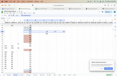
2) also as @ShootTheCore said, CPS2 has been fully reverse engineered, so any repair is just a matter of (lots of) time. I found the Full schematic very complex, I frequently use this awesome "what beeps with what" sheet that @WydD published here https://docs.google.com/spreadsheet...knL34eWvkaVA7-mJ8i6F27lmk/edit#gid=1029199072
3) lots of notes on various CPS2 repairs that might come in handy https://www.arcade-projects.com/thr...e-we-had-a-leaky-battery-repair-thread.19678/

The book of CP is a great reference for how stuff actually happens on CPS1/2 as well, normally If I read other peoples repairs and wonder "how did they know that the DL-2027 generates the graphics data, and how did they know that CGD and gfx-data-bus are the same thing???" that book has all the info in it.

Anyhoo

Assuming it IS the B board that is bad I'd probably do something like this

Its possible but unlikely that its a bad chip, much much much more likely to be a broken trace into or out of one of the chips. I've never had any luck spotting bad traces by visual inspection, testing with electrical tools is the only way that has ever worked for me,

So I'd be testing the most likely chips, in this case the Graphics chips

Graphics (all graphics are called characters on CPS2) are either Objects (Sprites) or Scroll Layers (Backgrounds)
the CGD (Character Generate Data gfx-data-bus) chip is DL-2027
the CGA (Character Generate Address gfx-add-bus) chip is DL-1927

Normally if the Addressing (CGA) was bad the background would draw at least something, probably garbled, but something.
So if the background is solid black I'd be looking at the Data (CGD = DL-2027) first

with Wydds awesome sheet I could look for the DL2027 column, find each pin, then look for the pins on other chips in that row that it needs to be connected to
So for example DL-2027 pin 117 needs to be connected to DL-1827 pin 101 and DL-1727 pin 34 and DL-1927 pin 114 and Also CN3 pin C25 (off-screen to the right)
Screen Shot 2024-03-22 at 9.03.30 PM.png
There are a quite a lot of pins on the DL-2027, so manually checking every single one by hand takes a lot of time.

To speed things up I sometimes use a logic probe or oscilloscope to quickly check a whole lot of pins, and then come back to the spreadsheet and beep out any that look suspect.

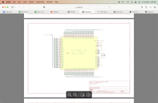
What does "suspect" look like CGD? For that the CPS2 reverse engineering schematic comes in really handy, normally I download the PDF version https://petitl.fr/cps2/93646B.pdf
then find the sheet that has the function of interest, in this case CGD=gfx-data-bus
Screen Shot 2024-03-22 at 9.23.54 PM.png
Bus lines are normally pulsing, so I would quickly Logic Probe each one, then come back and investigate the ones that were stuck high or stuck low
+5v are normally high, so if any of them aren't showing high with a logic prove I'd come back and look at those later too
GND lines are typically low, so if I get any other reading off the logic probe on those again I'd look more closely there

So that is the vast majority of the pins, still a few to look at by hand
on the DL-2027 the weird pins are Enable, AB, G1 and G2. These ones are doing conditional "stuff" and they dont always just pulse like the bus lines do.
A logic probe won't help much with these ones, an oscilloscope would, but anyone with an osiliscope that knows how use it probably won't read this far
So for those weird ones I normally look them up manually and beep them out.
In this example G2 on DL-2027 is pin 117; pin 117 needs to go to DL-1827 pin 101 and DL-1727 pin 34 and DL-1927 pin 114 and Also CN3 pin C25 like we discussed above. Not saying it IS G2 in this case, that's just the process I would follow

Good luck with the repair, would love to hear what happens next!
 
Not sure if this thread is still being followed. I am no longer getting any audio from my CPS2 setup. I don't know why but it seemed to have started recently. I have a DigiAV installed on my A board and I'm not even hearing audio out of the HDMI at the moment as well as the RCA ports on the board. I tried using the buttons to increase the volume but nothing seems to be happening. I have modded my boards to be inside of a jasenscustoms case. I'll have to open it up and see what is happening.
 
Not sure if this thread is still being followed. I am no longer getting any audio from my CPS2 setup. I don't know why but it seemed to have started recently. I have a DigiAV installed on my A board and I'm not even hearing audio out of the HDMI at the moment as well as the RCA ports on the board. I tried using the buttons to increase the volume but nothing seems to be happening. I have modded my boards to be inside of a jasenscustoms case. I'll have to open it up and see what is happening.

Did you go an extended period of time without using it?

Try holding volume down upon start up (hold volume down, turn on, keep holding until attract screen) then try to raise the volume to see if you get sound.
 
Yeah, it's usually sit there for a while without powering on. I'll try that thank you. But I have another board (no darksoft or digiav modded) that doesn't seem to have the issues. I just hold volume up on the board and it has sound.
 
Not sure if this thread is still being followed.

Bro, it is. I’m cool with asking for repair help & all but maybe you should start your own thread on your specific CPS2 issue.

It sounds like you have a super cap issue btw; just replace it & see if you get the ability to increase/decrease your sound levels back.
 
Fun! I do love a good CPS2 board repair, looks like great progress so far

Normally from here I would be thinking about
1) as @ShootTheCore suggested narrowing down the problem domain, check with another known good A board do confirm that the remaining problems are indeed on the b board
2) also as @ShootTheCore said, CPS2 has been fully reverse engineered, so any repair is just a matter of (lots of) time. I found the Full schematic very complex, I frequently use this awesome "what beeps with what" sheet that @WydD published here https://docs.google.com/spreadsheet...knL34eWvkaVA7-mJ8i6F27lmk/edit#gid=1029199072
3) lots of notes on various CPS2 repairs that might come in handy https://www.arcade-projects.com/thr...e-we-had-a-leaky-battery-repair-thread.19678/

The book of CP is a great reference for how stuff actually happens on CPS1/2 as well, normally If I read other peoples repairs and wonder "how did they know that the DL-2027 generates the graphics data, and how did they know that CGD and gfx-data-bus are the same thing???" that book has all the info in it.

Anyhoo

Assuming it IS the B board that is bad I'd probably do something like this

Its possible but unlikely that its a bad chip, much much much more likely to be a broken trace into or out of one of the chips. I've never had any luck spotting bad traces by visual inspection, testing with electrical tools is the only way that has ever worked for me,

So I'd be testing the most likely chips, in this case the Graphics chips

Graphics (all graphics are called characters on CPS2) are either Objects (Sprites) or Scroll Layers (Backgrounds)
the CGD (Character Generate Data gfx-data-bus) chip is DL-2027
the CGA (Character Generate Address gfx-add-bus) chip is DL-1927

Normally if the Addressing (CGA) was bad the background would draw at least something, probably garbled, but something.
So if the background is solid black I'd be looking at the Data (CGD = DL-2027) first

with Wydds awesome sheet I could look for the DL2027 column, find each pin, then look for the pins on other chips in that row that it needs to be connected to
So for example DL-2027 pin 117 needs to be connected to DL-1827 pin 101 and DL-1727 pin 34 and DL-1927 pin 114 and Also CN3 pin C25 (off-screen to the right)
Screen Shot 2024-03-22 at 9.03.30 PM.png
There are a quite a lot of pins on the DL-2027, so manually checking every single one by hand takes a lot of time.

To speed things up I sometimes use a logic probe or oscilloscope to quickly check a whole lot of pins, and then come back to the spreadsheet and beep out any that look suspect.

What does "suspect" look like CGD? For that the CPS2 reverse engineering schematic comes in really handy, normally I download the PDF version https://petitl.fr/cps2/93646B.pdf
then find the sheet that has the function of interest, in this case CGD=gfx-data-bus
Screen Shot 2024-03-22 at 9.23.54 PM.png
Bus lines are normally pulsing, so I would quickly Logic Probe each one, then come back and investigate the ones that were stuck high or stuck low
+5v are normally high, so if any of them aren't showing high with a logic prove I'd come back and look at those later too
GND lines are typically low, so if I get any other reading off the logic probe on those again I'd look more closely there

So that is the vast majority of the pins, still a few to look at by hand
on the DL-2027 the weird pins are Enable, AB, G1 and G2. These ones are doing conditional "stuff" and they dont always just pulse like the bus lines do.
A logic probe won't help much with these ones, an oscilloscope would, but anyone with an osiliscope that knows how use it probably won't read this far
So for those weird ones I normally look them up manually and beep them out.
In this example G2 on DL-2027 is pin 117; pin 117 needs to go to DL-1827 pin 101 and DL-1727 pin 34 and DL-1927 pin 114 and Also CN3 pin C25 like we discussed above. Not saying it IS G2 in this case, that's just the process I would follow

Good luck with the repair, would love to hear what happens next!

What an amazing start to help me diagnose this! Thank you for the head start. I beeped all these pins you referenced (including c25 on cn3) from pin 117 on DL-2027 & they all have continuity. So, it’s not a broken trace problem.

Wanting to rule out a SIMM issue, I did the unthinkable and decided to flash another game to some spare SIMMS I had, along with Avalaunch decrypted roms to repopulate this B board (forgive me!) Below is the result:

IMG_0628.jpeg
IMG_0631.jpeg

SIMMS wrote properly, so no issues there. However, I get the same missing background result, this time with these Progear roms. Trippy as f*ck seeing this play without the backgrounds lol! All inputs, sprites and music/sounds effects work perfectly.

Since pin 117 on DL-2027 has continuity, do you have anything else I could possibly check? Would one of the work rams in 3A or 4A cause this missing background issue? I hate not having any other B boards to test other than this one…

EDIT: by dumb luck, I actually found a NOS DL-1927 lying around my closet I got years ago (has been hermetically sealed in an antistatic bag)…wondering if this particular chip (as opposed to the DL-2027) will give me my backgrounds back given I have working sprites…think it might be worth trying to replace it? Stay tuned…
 
Last edited:
Did you go an extended period of time without using it?

Try holding volume down upon start up (hold volume down, turn on, keep holding until attract screen) then try to raise the volume to see if you get sound.
I think this was it. It wasn’t powered on for a long time and I just turned it on again today after this weekend and the sound was fine. Thanks for advice. And sorry about highjacking the thread. I just searched for cps2 issues and this thread seemed like a generic one for troubleshooting.
 
(Gill voice): RESURRECTION!!!!!

IMG_0636.jpeg
IMG_0638.jpeg
IMG_0641.jpeg
IMG_0642.jpeg
IMG_0647.jpeg
IMG_0648.jpeg

DL-1927 was the culprit. Swapped it out with a NOS I had forgotten about & all is good!


Also worth mentioning that I had to clean out corrosion out of the used sockets with a combination IPA/x-acto knife treatment, followed by a very strong vacuuming. I also reflowed the DL-2027 chip for good measure.

Was it worth the aggregate time I spent? Hell yes. I can’t believe I was able to get this up & running…wouldn’t have been possible without this forum & the very valuable contributors we have here.
 
Last edited:
Back
Top