Good point.Wouldn't it be possible to measure it on the real thing with a memory scope or logic analyser?
You are using an out of date browser. It may not display this or other websites correctly.
You should upgrade or use an alternative browser.
You should upgrade or use an alternative browser.
Custom JVS I/O - MEGA JVS
- Thread starter winteriscoming
- Start date
winteriscoming
Champion
I don't have any tools for that currently.Wouldn't it be possible to measure it on the real thing with a memory scope or logic analyser?
winteriscoming
Champion
I may do that if I can't figure it out by guessing.You could also set up an arduino and use that to measure the delay. A bit more work, that's a fact.

It seems to mostly be the Lindbergh that threw things off, making me incorporate a delay in the first place.
winteriscoming
Champion
F-ZERO AX has the weirdest control scheme with all kinds of analog inputs and buttons. With a little work using the MEGA JVS, I can get it playable in OR2SP's cab as follows:
Start button lines up to Start in game.
View Change is currently mapped to both a View Change button and the Boost button, though I don't think the View Change functionality does anything in-game. There are like 4 view change buttons on this game, so not sure.
Steering wheel is steering X axis.
Shifter up/down map up to the paddle left/right on the game that let you strafe left/right, though not sure how absolutely necessary this feature is... maybe in more difficult tracks?
Brake is brake.
Gas is mapped to both Gas and Steering Y axis. When you calibrate controls, you need to do so with gas slightly pressed it so that when it's released it equals Y down. When it's pressed in it equals Y up and Gas. I'm not seeing where Y movement is that integral to this game, but again, maybe in later races.
It's not the most ideal setup, but it's definitely nice having yet another racer to boot up in my cab.
freddiefiasco
Professional
If this game has its own profile will it override some of the default profile values? The reason why I ask, I believe the Deluxe cab had additional I/O that the Standard Cab doesn't even use. Hopefully that is not extra work on your side to even account for the Deluxe cab setup. (It might be the tilt feature that references the Y axis or Shifters)F-ZERO AX has the weirdest control scheme with all kinds of analog inputs and buttons. With a little work using the MEGA JVS, I can get it playable in OR2SP's cab as follows:
Start button lines up to Start in game.
View Change is currently mapped to both a View Change button and the Boost button, though I don't think the View Change functionality does anything in-game. There are like 4 view change buttons on this game, so not sure.
Steering wheel is steering X axis.
Shifter up/down map up to the paddle left/right on the game that let you strafe left/right, though not sure how absolutely necessary this feature is... maybe in more difficult tracks?
Brake is brake.
Gas is mapped to both Gas and Steering Y axis. When you calibrate controls, you need to do so with gas slightly pressed it so that when it's released it equals Y down. When it's pressed in it equals Y up and Gas. I'm not seeing where Y movement is that integral to this game, but again, maybe in later races.
It's not the most ideal setup, but it's definitely nice having yet another racer to boot up in my cab.
winteriscoming
Champion
At this point every profile is a complete mapping of controls, so every profile overrides what's loaded by default or what was loaded from a previous profile. Only the last selected profile is what drives the mappings at any point. Does that answer your question?If this game has its own profile will it override some of the default profile values?
I'm guessing the deluxe version wouldn't even be bootable outside of the dedicated cabinet. Has that version been dumped?The reason why I ask, I believe the Deluxe cab had additional I/O that the Standard Cab doesn't even use. Hopefully that is not extra work on your side to even account for the Deluxe cab setup. (It might be the tilt feature that references the Y axis or Shifters)
freddiefiasco
Professional
It sure does! Thanks.
I am not aware of if there is a separate version at all to be honest. I just know that when you are in the the test menu for the deluxe version, all the I/O registered when I triggered Off/On activity. When I compared to the standard version, the same I/O was visible but the cab itself did not have the same control panel for me to test.
I am not aware of if there is a separate version at all to be honest. I just know that when you are in the the test menu for the deluxe version, all the I/O registered when I triggered Off/On activity. When I compared to the standard version, the same I/O was visible but the cab itself did not have the same control panel for me to test.
winteriscoming
Champion
I am very happy to report that I've got a hardware solution in place for the analog jumpiness seen when the MIDI FFB board is on and gets worse when it's active. I had mostly addressed the issue with software analog smoothing doing a running average of values, but the hardware-based solution allows for much more responsive analog input, and I can ditch the software smoothing and free up cycles for other tasks.
I have to admit to being very inexperienced when it comes to circuit design and the various challenges that come up. It turns out that the analog issue can be fixed with a simple .1uf capacitor going from each used analog pin to ground at the 26-pin connector where the analog wires come in. It's a simple retro-fit on my current board, but I will be incorporating these into my next revision that I hope to finalize and order early next year. I believe typically the integration of a capacitor and a resistor (which I didn't include) is referred to as a low pass filter, and I only just came across this solution today.
The other things I'm contemplating at the moment are better debouncing/glitch filtering on the MEGA 2560 and possibly SD card integration for saving/loading profiles. There isn't a memory capacity issue with the MEGA 2560 as I think I'm currently using 12% of program storage space, but an SD card would make for easier profile editing and would allow for easier retention of last profile used, so that it would be loaded up the next time the board boots. It could also allow for some kind of mode that would allow you to create a new profile on the fly by pushing buttons, etc.
I could see something like on the fly profile creation working with the combination of the profile switch and the mini display. You go into game input test mode and then toggle the profile creation on the MEGA JVS. The board activates a given switch and displays it on the screen. You can tell if the switch is active in the game input test and then press the button on your control panel to map to it or skip to the next input by pushing the profile button. This would be the easiest way I can think to create a profile without having to look up wiring diagrams or guess and check.
So ideally the next revision would incorporate:
1. Header for small OLED display.
2. SD card slot (still need to test this to confirm it will work the way I want).
3. Capacitors for analog inputs.
I'm also currently working on driving the MIDI FFB with an Arduino, and there might be some benefit in having the capacity for that Arduino to speak with the MEGA JVS Arduino, so I likely will want to include some optional header for that - maybe keep a serial port open and dedicated to this optional purpose.
winteriscoming
Champion
I've started playing around with SD card integration in the software, and I'm finalizing the design for the V2 board.
V2 is going to be a slightly bigger footprint, but it will have:
-mounting holes for easier permanent mounting in a cab
-header for optional display
-optional display mounting directly to the board for those who will use it outside of a cabinet, but still want a display
-micro SD card module header for installing a module onto the board
-dedicated spots for 8 capacitors to go with each of the analog channels - necessary for driving cabs with high EMI from FFB units - otherwise optional
It's going to require some pin reassignment so final software will ultimately end up being incompatible with V1 boards (only a couple people have V1 boards at the moment).
I have decided to keep the board compatible with the Arduino DUE and potential future boards with the same footprint that may be 3.3v, but I will not be making the software compatible. DUE is officially retired anyway, and I've been able to accomplish even my tertiary goals on the MEGA 2560. MEGA 2560 is a better supported and cheaper board, so no reason to deviate. I may work on official DUE support after everything else is complete, but I kind of want to get this project finished so that I can move on to other stuff.
After using my MEGA JVS V1 almost exclusively in my driving cab for some time now, I'm pretty happy with the results.
I've got 2 anomalous issues I haven't started digging into. One is that MKGP2 is usually booting with 99 credits. It is somehow related to this I/O and doesn't happen 100% of the time. The other issue is that the start lamp seems to be activated by MIDI FFB activity. It will blink with different intensities according to communication going to the MIDI board. The I/O doesn't have anything to do with MIDI communication, so I believe it's an EMI issue and I'm hoping it can be resolved with a pull-down resistor on the associated MOSFET. Either that or the MOSFET has started going bad. It doesn't happen with the View Change lamp. This was happening before I started working on the NAMCO FFB translator, so it's not a new issue that came about as a result of that.
The main thing I want to change about the overall operation of the I/O is having it retain the last profile used. I'm addressing this in the V2 board with the inclusion of SD card functionality. There are times when I do a hard reboot on the cabinet and forget to change profiles. Most of the time it isn't an issue, but WMMT and MKGP when using force-feedback (another project I'm working on) utilize a specific output on the I/O, so the proper profile that uses the output needs to be active to get through boot checks. If an incorrect profile is active, the game can freeze for a few minutes while it spams FFB commands even after you hit the Test button to get back to the test menu. So that can be a bit annoying.
winteriscoming
Champion
Nothing to see here...The other issue is that the start lamp seems to be activated by MIDI FFB activity. It will blink with different intensities according to communication going to the MIDI board. The I/O doesn't have anything to do with MIDI communication, so I believe it's an EMI issue and I'm hoping it can be resolved with a pull-down resistor on the associated MOSFET. Either that or the MOSFET has started going bad. It doesn't happen with the View Change lamp. This was happening before I started working on the NAMCO FFB translator, so it's not a new issue that came about as a result of that.
")
I started thinking about this issue and looking into where in the software the start lamp gets lit. I use it as an indicator for several things, many to do with activity on the profile switch. I think a lot of noise was coming in on the profile switch causing the start lamp activity. The code required the profile pin to be held down for X amount of time before changing a profile, but the code to turn on the start lamp did not, so I was getting a lot of lamp activity with no other effects like random profile changes.
I had already worked debouncing into the code for the other switches and applying the same code to the profile switch seems to have taken care of the errant start lamp activity when the MIDI FFB is active.

Edit: In my V1 design I did not include pulldown resistors for the MOSFETs outside of the one that drives the JVS Sense line. My understanding is that in a low state, a floating MOSFET can potentially switch states like in an noisy electromagnetic environment, so a pulldown resistor is used to keep it low when not activated. I figured the Sense line should probably have that protection, but the other outputs that drive lamps and such probably don't need it. I haven't seen any non-software related errant activity on my lamps in all of my testing, but I am going to go ahead and include spots for a pulldown resistor for each of the outputs that will essentially be optional to install. I have space on the board and resistors are cheap, so why not?
Last edited:
I assume you have long wires between that switch and the arduino input that is pulled to gnd by it?
You might place a small bat85 diode in serie with that signal wire. Such will also protect the input against incoming voltage (either due to EMI or due to misconnection) A 330 ohm resistor in serie can limit the current. If during software development the controller pin is accidently set as output and high, you won't overload it if you press the switch. Finally, a 100nF capacitor to gnd can remove most of the EMI picked up by the wire. It's not like the response time of that switch is very important.
The original JVS board uses opto couplers between the microcontroller and the inputs, which in my opinion is overkill, specially since the GND and 5V are common for the opto led and transistor.
Professional equipment need to pass all kind of EMC tests so that they can put the CE mark on it (to allow selling it in Europe) A few minor adjustments like those I mention above can already make a world of difference. It's not like those components will increase the price much. If your pcb is on it's way, my advice comes 2 late.
winteriscoming
Champion
Another interesting update: A previous test left me scared about applying external power to the Arduino while simultaneously plugging in USB power from the PC. My previous test ended up frying the Arduino.
I just had my board out for troubleshooting the start lamp issue mentioned in the previous post, plugged it back in with the external power while simultaneously plugging in USB for programming it without thinking. I just now realized the board was still powered after I unplugged USB, and apparently the onboard management of power sources when both are available is working. Maybe I had polarity reversed in the previous test.
I just tried plugging and unplugging USB a few times while the 12v source was on, and it registered on the PC without any interruption to JVS communication.
At any rate, it seems to have no ill effect when the external 12v is powering it while USB is plugged in, too.
winteriscoming
Champion
In a cabinet, yes, the profile switch would have long wires between the board and the switch, and that is the case in my current setup. That is the case with all of the switches in the cabinet. For simplicity in design I make use of internal pullup resistors for all inputs, so that a pin just has to be grounded to be activated.I assume you have long wires between that switch and the arduino input that is pulled to gnd by it?
It would probably be best to have these hardware solutions tied to every input. Component cost isn't an issue, but space on the board is, especially if I want to stick with through-hole components for easy assembly. If I'm counting correctly, I think I'm dealing with a potential of 28 inputs coming from a Type 1 harness, plus any MEGA JVS specific inputs like the profile switch and a couple of optional switches.You might place a small bat85 diode in serie with that signal wire. Such will also protect the input against incoming voltage (either due to EMI or due to misconnection) A 330 ohm resistor in serie can limit the current. If during software development the controller pin is accidently set as output and high, you won't overload it if you press the switch. Finally, a 100nF capacitor to gnd can remove most of the EMI picked up by the wire. It's not like the response time of that switch is very important.
Testing up to this point, even with the MIDI FFB active, makes me think software debouncing is sufficient for the inputs, but I'm currently only testing in a driving cab, not a fighting cab, for example.
I haven't finalized V2 and submitted it for ordering yet, so I am open to your suggestion. I just have to see if I fit everything. I haven't found much info on hardware debouncing for figuring out the component values as they relate to response time. Would you have any advice to offer for the inputs where I want to filter out noise and debounce, but still be very responsive?It's not like those components will increase the price much. If your pcb is on it's way, my advice comes 2 late.
usually if they both have common earth that should avoid any problem.
What could also happen is that you unplug the sun and then it's the arduino powering everything and that could be too many mAmps and fry the Arduino.
My two cents.
What could also happen is that you unplug the sun and then it's the arduino powering everything and that could be too many mAmps and fry the Arduino.
My two cents.
winteriscoming
Champion
How I've handled powering components is that the Arduino is only responsible for powering some things and has worked fine under just USB power in all of my tests:usually if they both have common earth that should avoid any problem.
What could also happen is that you unplug the sun and then it's the arduino powering everything and that could be too many mAmps and fry the Arduino.
My two cents.
-OLED Display
-Analog input voltage
-RS485 Module
-MOSFETS for driving outputs
-Inputs - internal pullup
Outputs themselves are powered by external sources. If the 5v plug from the cabinet is not plugged into the MEGA JVS, then no 5v output lamps will light. It's the same with 12v outputs, however 12v also goes to the onboard regulator for externally powering the Arduino.
It was actually the reverse scenario that killed my previous Arduino, where it was powered by USB and I hot plugged the 12v source, but potentially with polarity reversed - I can't be sure because I didn't have a mating header installed at the time. Even with a mating header, it's still possible to accidentally reverse the polarity when hot plugging because the pins will make contact even if the connector won't lock in that position.
winteriscoming
Champion
I did find this page with a lot of info on debouncing.You might place a small bat85 diode in serie with that signal wire. Such will also protect the input against incoming voltage (either due to EMI or due to misconnection) A 330 ohm resistor in serie can limit the current. If during software development the controller pin is accidently set as output and high, you won't overload it if you press the switch. Finally, a 100nF capacitor to gnd can remove most of the EMI picked up by the wire.
They've got some formulas there to figure out values and this circuit for the most protection:
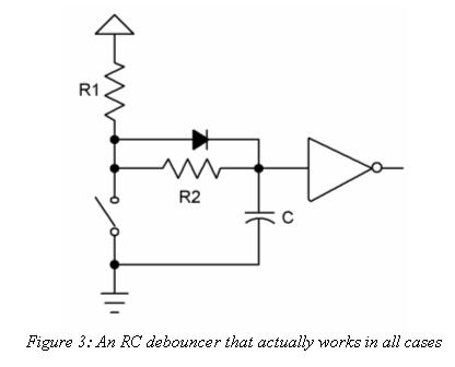
I guess the issue I have is the changing everything to external pullup and potentially having to add 4 components per input that I don't have on the board now. 30 inputs puts me at 120 additional components. I don't think I'll be able to make them fit with through-hole.
Let me just put it out there. This board is being developed by an amateur who is figuring things out as he goes.

It's unclear why your first Arduino hot fried when you connected both usb power and external power. The arduino was designed to allow powering it from both external and usb. Maybe your first arduino (clone?) had a fault in it's power supply circuit. The arduino leonardo (The one I normally use) has a diode on it's external power input that should conduct if it's reverse polarised. If you have a beefy supply (like an arcade sun) it will turn that diode into a led for a fraction of a second. After that, it will turn the rest of the electronic components into high temperature liquid silicium.Another interesting update: A previous test left me scared about applying external power to the Arduino while simultaneously plugging in USB power from the PC. My previous test ended up frying the Arduino.
I just had my board out for troubleshooting the start lamp issue mentioned in the previous post, plugged it back in with the external power while simultaneously plugging in USB for programming it without thinking. I just now realized the board was still powered after I unplugged USB, and apparently the onboard management of power sources when both are available is working. Maybe I had polarity reversed in the previous test.
I just tried plugging and unplugging USB a few times while the 12v source was on, and it registered on the PC without any interruption to JVS communication.
At any rate, it seems to have no ill effect when the external 12v is powering it while USB is plugged in, too.
A thing that could go wrong is if you use an ungrounded pc. The potential of it's ground can be different from the potential of the arcade you connect it 2. If you plug in the usb and the 5V makes connection before the GND, you can have problems as the potential difference will cause a current flow trough vcc. The usb data line pins are made shorter to ensure that the 5V and GND make contact first. A good practice to avoid such problems is connecting a GND wire between the pc you use and the arcade machine GND. A desktop pc should have such a connection as it's case is grounded. The arcdade should be grounded as well.
Considering the debouncing. Whenever you use hardware or software debouncing, it will always introduce a short delay in response time. In software, you can adjust the debounce timers and check if everything still works fine. In hardware, it's not that easy. If you close the button, the debouncing capacitor will discharge trough the resistor and the voltage at the input of the arduino uC will drop. The curve dV / dT is exponential, as in the beginning the discharge current will be high (You still have the full 5V that causes current trough the resistor. At the end, as the voltage is lower, the current will be lower as well. At some voltage, the uC will see the input as low. (active)
Usually, trial and error is what I use. I have 1K resistors and bat85 diodes in serie with my inputs. You could try some capacitors like 1nF, 10 nF, 47nF and 100nF and see if you notice some delay. Temporary remove the software debouncing and count how many pushes are detected. If you push the button one time and see multiple counts, your capacitor is to small. Not all buttons have equal debounce behavour which is why it's not an exact science.
Another thing puzzling me is why you are so afraid of smd. As long as you don't use the smallest 0402 components, most are still pretty easy to solder. They usually are cheaper than their wired family members. If you make your own prototype pcb, you can skip some of the (boring) drilling work. If you intend to sell it as a "assemble it yourself" package, I can understand. All I do is leave my fingernail of my pointing finger long so I can use it to hold the smd while I fix one end with some solder. Once it's fixed, you can solder the other end properly (or the other pins). Once that's done, the fixation soldering is redone properly as well. You just need some thin solder wire and a small tip on your iron. If you can find a bottle of non corrosive flux, it's a good aid as well.
Wow, this is becoming a long post. Congrats to those who made it till here...
winteriscoming
Champion
That's my main concern. I like the idea of it being easy to assembly for everyone. I would probably like to experiment with SMD components, but maybe in a future revision. @Darksoft wants me to design the board where everything is on one board, and the Arduino and modules are eliminated, but I doubt I'll go that far.If you intend to sell it as a "assemble it yourself" package, I can understand.
Considering the debouncing. Whenever you use hardware or software debouncing, it will always introduce a short delay in response time. In software, you can adjust the debounce timers and check if everything still works fine.
I think since software debouncing is working, I will probably just stick with that for now.Not all buttons have equal debounce behavour which is why it's not an exact science.
I think the most risk for damage in my entire design is to the Arduino itself, so hopefully it can be easily replaced in the event of some kind of failure. I suppose something could go wrong and fry the JVS port of the game motherboard, but I'm not sure what would cause that. In all cases, I'll just say assemble and use at your own risk.