What's new

RetroRGB

Student
Joined
Jul 21, 2015
Messages
40
Reaction score
69
I have two tabletop arcade machines with a 14" CRT built in that both have the same issue: The image won't fill the screen. I recapped one of them and it was zero change. I tried tweaking the POTs and was able to stretch the image wide enough to overscan and while it's not ideal, it won't really take away from gameplay.

The vertical adjustments are still off though; I can stretch it, but can't get it low enough to fill the bottom of the screen. I tried replacing the 5k vertical adjustment POT with a 10k, but it does the exact same thing...one I hit about 5k of resistance, the image stops moving down.

I'd like to at the very least fix the vertical position, but since this CRT is practically brand new, I'd love to get both horizontal and vertical as good as I can. I believe I'd just need to switch out two capacitors with different values to fix this, but I couldn't find any information on this chassis anywhere.

Can anyone here offer suggestions?

Original Geometry - Top is fine, but left, right and bottom aren't fully used:
https://i.imgur.com/kdjlnKn.jpg
https://i.imgur.com/g1cgkh4.jpg

Current Geometry - It's not bad, but there's a LOT of the top cut off, so being able to "lower" it more is the minimum goal for me:
https://i.imgur.com/NpIqKS2.jpg

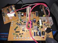
Chassis, pre-recap: https://i.imgur.com/McWxZys.jpg

Neckboard: https://i.imgur.com/xP4ATBA.jpg

Tube: https://i.imgur.com/Xc0Sj8F.jpg


4gf0mGw.jpg
 
OK. Here are the caps you need to add / change. They are in RED (NOT the Diode!!!!).

The cap in YELLOW is a maybe..... Its odd there is no jumper for W or N (WIDE or NARROR) settings.

Can you post a picture of the PCB TRACK side. SO i can see were the caps connect to?? SO i can work out if YELLOW will need to be modded...

ALSO it looks like the main fuse on the PCB just has a wire link on it?? I'd replace it with a proper fuse and holder...

T.
 

Attachments

  • CHASSIS.jpg
    CHASSIS.jpg
    739.6 KB · Views: 259
Last edited:
Thanks so much for responding. I'll have to take it apart again tomorrow to better pictures of everything, but below is what I have so far.

Also, I have two of these machines and both chassis are like this: Missing C442, C435 and the fuse. I'll order the fuse with the new caps and will try to have good pics of both sides of the board and components.

1RQtaxr.jpg

yJw4V4h.jpg
 
I'm 99% sure the YELLOW one does NOT need to be changed... Only the RED ones.

Work out what the current values are and buy replacement a few values higher and lower. That will give you heaps of values to play with. Try getting a higher voltage rating as well. Some Film capacitors are hard to find... But last time i got a heap for work from Farnell (Element14) I'm sure EBAY would have them tooo...

T.
 
Okay, I just disassembled everything.

Back of board (with component labels): https://i.imgur.com/lmG3Iqt.jpg

C437: https://i.imgur.com/bJdUx2b.jpg

C441: https://i.imgur.com/YQoGF2u.jpg

I also ordered one of the boards @mmmonkey suggested, just in case this becomes too complicated...but I think there's a few of these cabinets / chassis in the wild, so if we figure it out, it'll benefit other people.

After seeing the board layout, can you confirm C437, C438 and C441 are what needs to be changed?
 
Yes, Its the caps marked in RED. ( C438 and C442 ) plus if you need them the 2 blank spots as well ( C435 and C441).

T.
 
Okay, so remove C438 & C441, check their capacitance and order values below and above it, with the same or better voltage tolerance.

How would I know what to put in the blank spots 442 & 435?
 
OK. If my maths are correct..

C438 (123J) is 12nF (1600V)

C441 (684J) is 680nF (250V)

You can leave the blank spots empty. There only there so you can add 2 values together to get a non standard capacitor value... You don't have to use them.

All you need to do is buy more caps above and below these values. I ALWAYS start with a LARGER value.. and go from there....

Search Google for "capacitor standard values chart" and that will let you know the values you can buy above and below these values.

T.
 
OK

digikey.com/product-detail/en/…H16153JV/P10509-ND/269129 is OK (15nF) But i would look for a higher value aswell.

22nF is here (an example) https://www.ebay.com.au/itm/10pcs-0-022uF-223J-1600V-22NF-CBB-Metallized-Film-Capacitor-P-20MM/291659975358

-------------------------------

https://www.digikey.com/product-det...tronic-components/ECQ-E2824KF/EF2824-ND/56489

820nF is OK.... I just hope the jump to 820 nF isn't to high.... You may have to get like some 100nF an use both positions to add 100nF to the already 680 giving you 780. OR a 56nF to give 736nF.

You will just have to use trial and error and see were the "sweet" spot is value wise..... BUT i would definitly get some 100nF and 56nF caps.

T.
 
Okay, I'll look for those components on Digikey in the US and try to find exact matches. Also, someone was recommending I try adjusting the centering rings of the CRT and not touch the caps. Any thoughts on this? I'd probably want to replace them with quality ones anyway, even if they were the same value.
 
I'm not sure if you can move the pic quite that much with the convergence rings. You'll also mess with purity and convergence which can be a PITA to get back to looking good. Your convergence looks pretty spot on (blue is slightly off vertically, that's something you can definitely fix).
 
I would NOT touch the rings. You can stuff it up if done wrong. Its tooo much of a risk. Plus.... the tube looks good... Only other thing to adjust would be a tad of "Focus" on the flyback transformer (might be hard to get to were the chassis is in your cab....)
 
Jomac is VERY good at what he does. I have sent many people his way. It would seam a waste of 2 chassis... to not mod them and see how they go.... I mean you "could" get a replacement chassis and still have simular issues... I would hope not... but its still possible.
 
Okay, the two caps I ordered came in and there's a few things to note:

- It didn't seem to move much lower. I guess I did need a higher value. How about this?: https://www.digikey.com/product-det...nic-components/ECW-HA3C223J/P15425-ND/3088422

- Now it's a bit too wide. I'm assuming this is the 820nF cap, as @GC8TECH already warned me it might be too high. I might just want to put the original back in, as I can't seem to find a 780nF cap on Digikey. Or just add this next to it, I guess: https://www.digikey.com/product-det...onic-components/ECQ-E2563JF/P14611-ND/2567739

- Even though it's "too wide", I still get this issue on the side. Is that the rings? Both this and the other one do the same thing:
If so, the original 680nF/250V cap was probably right and I might as well just order a new one of those: https://www.digikey.com/product-det...onic-components/ECQ-E2684JF/P14598-ND/2567732


...also, I agree that I'd rather not replace this chassis, as it's otherwise in good condition and I already recapped the whole thing. LOL and bought enough caps to do my second one as well!
 
So it "did" move it a tad lower?? yeah grab the 22nf thats in the link. i would grab a couple of them.. since you can add 22nF to the width as well... You can also install 2 caps to add there value together if you need to. But if you can get away with just 1 cap.. then that great. Thats why they have the 2nd spot on each adjustment. Personally i would only adjust 1 at a time.. to make it easy to see progress...

On the wide side... the "curl" when you go to far to the edge of the screen is NORMAL......

T.
 
I'm honestly not sure. I think it moved a bit, but not much lower. I'll try the new cap I just posted and see.

Also, I've never seen the "curl" before on any CRT I've owned....every other CRT just over/underscans like the other two sides. There's no way to adjust that?
 
Back
Top