Home Arcade System

The cable would have to make use of pin #9 of the HD-15, and it looks like the Retro Upgrades cable doesn't use it. The RT cable definitely doesn't use it, as stated earlier.

The mod would be simple; you would need to provide the +5V to the Scart head as in the diagram above. You could install a USB type A socket/female cable in the Scart and tap power from the HAS using a USB-C to USB-A cable.

Ah, thanks very much, OK. So, I need a 180 ohm fuse for that mod.

What you said about a USB cable reminded me, I did come across this one from Arcade Express yesterday, would it work?

1767547907561.png


https://www.arcadexpress.com/en/vid...RH7IGxUW6y1qwiatQjcfMPBFZH1y30kpVzZxh4aBhaR-4

Thanks
 
The cable would have to make use of pin #9 of the HD-15, and it looks like the Retro Upgrades cable doesn't use it.

Hi again @RGB. So, Will said,

"Our cable is the same as the diagram your shared, with some differences:
1. audio is connected to a 3.5mm audio breakout
2. we do not use VGA pin 9 as for some devices it is N/C. For this reason, we use VGA pin 14 for SCART pin 16 blanking voltage with no 180 ohm resistor so all devices are supported (the end result for SCART pin 16 is the same).
3. on our cable, pin 8 is N/C. same end result as with the diagram you provided as 0-2V on SCART pin 8 = OFF.

So in summary... Besides audio, yes our cable is the same as this diagram".

So, I'm confused. Does this mean his cable will work?
 
Ah, thanks very much, OK. So, I need a 180 ohm fuse for that mod.

What you said about a USB cable reminded me, I did come across this one from Arcade Express yesterday, would it work?


https://www.arcadexpress.com/en/vid...RH7IGxUW6y1qwiatQjcfMPBFZH1y30kpVzZxh4aBhaR-4

Thanks
This is neat, since it addresses the issue for the EU-based MiSTer users, but for the HAS, you need a USB-C cable. You could mod one of your cables using this - aliexpress.com/item/1005003099225077.html

Black wire is GND, red is +5V. You need a 180 Ohm resistor, not a fuse. If you open the Scart head and post the picture here, I can mark exactly where you should solder.

2. we do not use VGA pin 9 as for some devices it is N/C. For this reason, we use VGA pin 14 for SCART pin 16 blanking voltage with no 180 ohm resistor so all devices are supported (the end result for SCART pin 16 is the same).
There is nothing on pin #14 on the HAS end (looks like RU use VSync for that purpose, and the HAS doesn't output separate H/V signals, only CSync on #13), that's why it doesn't work.
 
This is neat, since it addresses the issue for the EU-based MiSTer users, but for the HAS, you need a USB-C cable. You could mod one of your cables using this - aliexpress.com/item/1005003099225077.html

Black wire is GND, red is +5V. You need a 180 Ohm resistor, not a fuse. If you open the Scart head and post the picture here, I can mark exactly where you should solder.


There is nothing on pin #14 on the HAS end, that's why it doesn't work.

Thanks. It seems like an active (I just read that many cheap adapters are passive and don't do the job correctly) USB to USB C adapter would also work with that Arcade Express cable, right, @RGB?

Black wire is GND, red is +5V. You need a 180 Ohm resistor, not a fuse. If you open the Scart head and post the picture here, I can mark exactly where you should solder.

Noted, thanks. If I feel up to it and figure out how to open the scart up safely, I will come back to you on this.
 
Thanks a ton @RGB, as usual your products are top notch and I know this is an issue with the BVM, not your products.

As an aside, this new cable from Mike Chi:

https://www.retrotink.com/shop/hd2bnc

Would it work with the HAS 5.1? It seems the H/V are split on it, so I'm not sure if it would still work as you just said H/V are not split on the HAS.
 
Thanks. It seems like an active (I just read that many cheap adapters are passive and don't do the job correctly) USB to USB C adapter would also work with that Arcade Express cable, right, @RGB?
You actually want a passive one in this case, since the USB-C on the HAS outputs +5V only, it doesn't need any voltage negotiation. If you can solder, I'd order the USB-C cable from my link and mod one of your Scart cables, that just three solder points in total.
 
Oh, and another beginner question, pin 13 on the HAS v5.1 is Csync, so is that like Sync on Composite? Would it indeed need a Sync Splitter? I think CSYNC means "pure" sync, not using the composite, but just want to make sure.

If that is the case, it explains why a sync splitter on the HAS for me didn't make a difference for the Sony 20L5 I was testing.
 
Thanks a ton @RGB, as usual your products are top notch and I know this is an issue with the BVM, not your products.

As an aside, this new cable from Mike Chi:

https://www.retrotink.com/shop/hd2bnc

Would it work with the HAS 5.1? It seems the H/V are split on it, so I'm not sure if it would still work as you just said H/V are not split on the HAS.
This will work just fine. You just don't connect VSync, and HSync=CSync.
 
Oh, and another beginner question, pin 13 on the HAS v5.1 is Csync, so is that like Sync on Composite? Would it indeed need a Sync Splitter?
This is Composite Sync, no stripping needed. Stripper is used for the Composite Video.
 
You actually want a passive one in this case, since the USB-C on the HAS outputs +5V only, it doesn't need any voltage negotiation. If you can solder, I'd order the USB-C cable from my link and mod one of your Scart cables, that just three solder points in total.

Ah, cool, thanks. Again, I'd have to come back to you on that as I would need a clear guide with it all. I an do basic soldering now, aye.
 
Man, I have so many wonky PCBs with weird sync. I also picked up a cheap/small oscilloscope, so if you (or anyone) ever needs me to test anything on these weird PCBs, let me know. As long as you walk me through it, I will do so!
 
Black wire is GND, red is +5V. You need a 180 Ohm resistor, not a fuse. If you open the Scart head and post the picture here, I can mark exactly where you should solder.

Hi bud,

Would I need to open the scart end only, or both VGA and scart ends? They seem moulded shut, so not sure how I would open either end.

And for the USB mod, I assume I'd need to slice into/ get wire out from part of the TINK cable, is that right?

Thanks
 
Hi bud,

Would I need to open the scart end only, or both VGA and scart ends? They seem moulded shut, so not sure how I would open either end.

And for the USB mod, I assume I'd need to slice into/ get wire out from part of the TINK cable, is that right?

Thanks
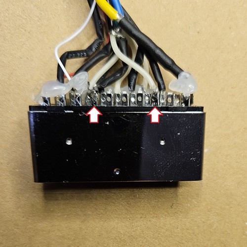
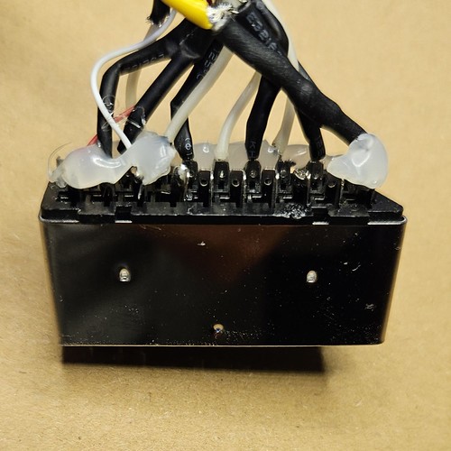
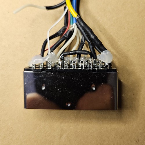
Here's a tutorial on how to mod the RetroTINK HD15 to Scart cable for the EU/AU TV sets:

1. This is how it should look when you open it. Notice the orientation.
55030814601_8cc6c29b3d.jpg


2. Locate pin #8 (switch) and pin #16 (blanking), cut/desolder these wires, and insulate them so that they don't touch other wires/pins inside the Scart head. Refer to the Scart pinout to be 100% sure you have found pins #8 and #16.
55030819496_883e221b60.jpg
55031074384_f4ed60b9b2.jpg


3. Solder a 180 Ohm resistor between pin #8 and pin #16.
55029921732_fbf1655b66.jpg


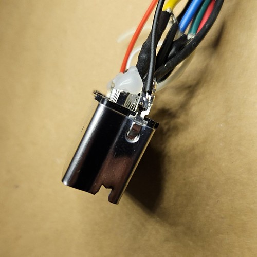
4. Now, you will need to solder your power cable (USB-C type, red wire is +5V, black wire is GND). Solder +5V to pin #8 and GND to one of the ground pins. I chose the shield (grounds are all interconnected inside the TV anyway).

55031150805_237b66405f.jpg
55031150825_c4e5f2a057.jpg


It might be a good idea to add a bit of hot glue on the exposed connections.
 
Last edited:
To open on the scart end unscrew the cap over the wire and once done it should let you take off the split plastic. You would end with the scart head as shown in rgb’s first picture
 
Here's a tutorial on how to mod the RetroTINK HD15 to Scart cable for the EU/AU TV sets...

To open on the scart end unscrew the cap over the wire and once done it should let you take off the split plastic. You would end with the scart head as shown in rgb’s first picture

Thanks a lot, both.

4. Now, you will need to solder your power cable (USB-C type, red wire is +5V, black wire is GND). Solder +5V to pin #8 and GND to one of the ground pins. I chose the shield (grounds are all interconnected inside the TV anyway).

Is there a version of the mod where I don't need to use a USB cable, @RGB?
 
Thanks a lot, both.


Is there a version of the mod where I don't need to use a USB cable, @RGB?

The idea of this mod is to add power to the Scart plug so that your TV set can display the RGB video. The USB-C cable seems like the easiest route, since it can be connected to the HAS alongside the audio and video cables. You could add a USB socket instead or even a barrel jack socket for an external power supply, but to me, that seems less practical.
 
The idea of this mod is to add power to the Scart plug so that your TV set can display the RGB video. The USB-C cable seems like the easiest route, since it can be connected to the HAS alongside the audio and video cables. You could add a USB socket instead or even a barrel jack socket for an external power supply, but to me, that seems less practical.

Thanks. Sorry, I just saw point 4. where you mention soldering the USB-C cable for power. Can it not be done without the USB-C cable somehow to keep things neater and have one less thing to plug in?
 
@RGB I have a conundrum recently experienced with a 4.1 HAS I’ve been using quite often. Tonight, my P1 button inputs from P1 through P6 stopped working.

P1 directional inputs and coin/p1 start work; just none of the input buttons do. I tried reflowing the 15 pins on the bottom of the DB15 connector and P1 buttons 1-6 still wouldn’t work.

I think there’s a problem with the older HAS I have as the HAS 5.0 I also use works beautifully with my boards - no issues with inputs there.

Any idea on what could be causing my P1 buttons 1-6 to completely not register all of a sudden with the HAS 4.1?
 
@RGB I have a conundrum recently experienced with a 4.1 HAS I’ve been using quite often. Tonight, my P1 button inputs from P1 through P6 stopped working.

P1 directional inputs and coin/p1 start work; just none of the input buttons do. I tried reflowing the 15 pins on the bottom of the DB15 connector and P1 buttons 1-6 still wouldn’t work.

I think there’s a problem with the older HAS I have as the HAS 5.0 I also use works beautifully with my boards - no issues with inputs there.

Any idea on what could be causing my P1 buttons 1-6 to completely not register all of a sudden with the HAS 4.1?
Try resetting it.

You can consider this a full device reset. It will erase the layouts for both Player 1 and 2. To do the reset, press and hold down both Player 1 and

Player 2 START buttons while powering on the HAS.

Side note: Once you perform the full device reset,the button layout will be blank, and you will need to enter the button configuration mode and set

your new button layout.

Instructions here:

https://rgbslab.com/pages/has-instruction-manual
 
I’ll have to try that; thank you for the advice. I originally tried resetting the P1 button layout by holding Start + two buttons down but realized in anguish none of the button presses were registering. :/ Will give this a shot early this week & report back here.
 
Back
Top