Home Arcade System

The problem is that a few 6 button CPS2 games (Vampire Savior is definitely one, but scant rumors of 1 or 2 others) are still sampling 4 JAMMA buttons instead of only the first 3 for punches. If the supergun has Kick 1 from the kick harness wired up to JAMMA button 4, a command super in VSav will be canceled when the game sees activity on JAMMA button 4.

If the HAS mapping can't get around this, the cheap/dirty fix is to throw a piece of tape over the CPS2 JAMMA edge at button 4 & 5 when playing Vampire Savior.
-ud
As I'm a little thick, button 4 on both kick and edge=no good?
 
Guys, I received another complaint about the button layout in HAS. I really don't know how to stress this, but the button layout can be remapped! Button remapping is listed as a feature in the product description and it's described in the instruction manual, too. I thought this was the main selling point of this supergun :)
 
Guys, I received another complaint about the button layout in HAS. I really don't know how to stress this, but the button layout can be remapped! Button remapping is listed as a feature in the product description and it's described in the instruction manual, too. I thought this was the main selling point of this supergun :)
Is there a link to the manual in the first post? I had to read the RECO instructions to figure out the remapping procedure. I forget if any printed instructions came with the supergun as it's been quite a while since I got mine.
 
  • Like
Reactions: RGB
Hey RGB, what about adding BJTs, such as for buttons 6?
Could that solve the issues?
 
Hey RGB, what about adding BJTs, such as for buttons 6?
Could that solve the issues?
Do you mean the issue with Vampire Savior? The only solution for the current design, is to install a switch/jumper to separate JAMMA button 4, because I've used all I/Os of the microcontroller. The transistor solution that you see for button 6 is just to have the JAMMA button 6 (pins #3 and #27) separated from the kick harness button 6. Basically, this makes the supergun compatible with those multi-pcb boards that accept up to 6 buttons via the JAMMA edge, and with standard JAMMA that normally grounds JAMMA pins #e and #27.
 
Hey RGB, what about adding BJTs, such as for buttons 6?
Could that solve the issues?
Do you mean the issue with Vampire Savior? The only solution for the current design, is to install a switch/jumper to separate JAMMA button 4, because I've used all I/Os of the microcontroller. The transistor solution that you see for button 6 is just to have the JAMMA button 6 (pins #3 and #27) separated from the kick harness button 6. Basically, this makes the supergun compatible with those multi-pcb boards that accept up to 6 buttons via the JAMMA edge, and with standard JAMMA that normally grounds JAMMA pins #e and #27.
Understood. Thanks for your explanation. :)
 
Maybe it has been answered before, didn’t read the full 38 pages of this thread...

If I would use a Saturn controller and adapter, would the shoulder buttons we mapped to coin/test or something on the DB15 pinout?
So can I map those as well in addition to the regular 6 buttons?

Thanks!
 
Hey, check out the layout:

Saturn -> NeoGeo/DB15
A -> 4/D
B -> 5 (DB15 pin #2)
C -> 6 (DB15 pin #10)
X -> 1/A
Y -> 2/B
Z -> 3/C
Start -> Start
L -> coin/select (DB15 pin #3)
R -> unused

The adapter doesn't have the remapping functionality, but you can change the mapping using HAS. If you want to use it with some other supergun, I can map it differently if you need :)
 
cool, should work then I think, but my Saturn is not a stock Saturn HSS-0136 stick anymore, I installed a MC Chtulhu and mapped the buttons like a normal cab, so
P1 - P2 - P3 - P4
K1 - K2 - K3 - K4

Any idea if that would map the same on your adapter>
So would give me;

1-2-3-coin
4-5-6-unused
 
Not sure. Could you give me the DB15 pinout you'd like to have? Ideally formatted in the same way as in my previous post, so Saturn controller button -> DB15 pin #.

If you want, we can carry on this discussion via PM :)
 
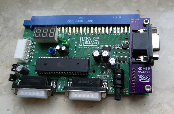
Finally received my PCBs from OSH Park :)

40491484562_7681d11bd3_z.jpg


With this adapter you can connect HAS with the OSSC using a standard VGA cable.

You can also use a VGA->BNC cable to connect it directly to PVM/BVM monitors.

Order the PCBs from here. If there is enough interest I can start stocking those, too.

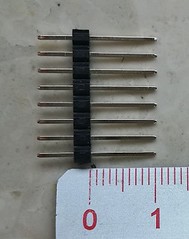
Edit: The adapter comprises of a female VGA connector (HD15) and a 1x8pin 18mm goldpin header. The header pins need to be moved a bit so that you end up with 10mm long pins that connect to HAS, and shorter ones that will go to the adapter. You will also need two 15mm long screwed spacer sleeves and bolts to install the adapter.
39823893754_6ed85b440f_m.jpg
 
Last edited:
I'm in for it, if you can produce them
I have the last HAS version and an OSSC
If there isn't enough demand I'll source it by my own :(
 
I would get one as well :)

It's outputting always automatically TTL sync or depends on the HAS setting?
 
What's the advantage of using VGA to VGA to OSSC versus the mini 8 pin din to scart to OSSC?
The 8 pin DIN does not work with the OSSC due the input stage on the OSSC when using SCART.

edit: This only applies to the TAITO F3
 
Last edited:
  • Like
Reactions: RGB
Back
Top