What's new

Pap

Beginner
Joined
May 1, 2020
Messages
15
Reaction score
6
Location
Poland
Hey, it is a real pain to buy a cable plus shipping which is the price of another cable so i wanted to make my own cable
i have a bunch of 8pin male connectors and high quality scart cables that can be cannibalized. I want to use the cable only for my MINIGUN with 8pin din (i ordered the PCBs and parts just few days before 9pin version was posted:D, my luck)
But since i'm not that much familar with all the possibilities i have some questions:
  1. I pretty much follow the pinout i have here:
    1665701902004.png

    I assume this will be okay?
  2. I'm not sure what is the difference between TTL sync and Csync even though i tried to read about i just dont get it how it works technically, people just say what are some differences between them but not in detail how they both work?
  3. I plan to use the cable mainly on my old RGB CRT TV, possibly a SCART switch. In the future i will probably buy something like OSSC or some retrotink box. I heard stories that not all cables work with some of these devices, and sometimes you can even fry them? how to avoid that how to work with that? It has something to do with this sync issue?
  4. is the COMPOSITE VIDEO (pin20 on scart) considered the SYNC pin on 8PIN connector? what about that TTL CSYNC shenanigans?
  5. do i really have to ground all those pins? 5,9,13,17,18,21(case) togethere? i read somewhere that this is not necessary as long as the 18 and case-pin are grounded together?
  6. can i ground audio-ground to the regular ground ? i dont intended to split the audio signal outside the scart so maybe i dont need that ground at all?
 
Hi another Minigun fan! I will do my best to help.


Lots of questions, answers in-line to keep it brief
  1. I pretty much follow the pinout i have here:
    I assume this will be okay?
Yes, that's the same one I used, works fine. Only thing to be aware of it that SCART pinouts are a bit inconsistent for plug/socket. Easier with SCART because it it keyed.
  1. I'm not sure what is the difference between TTL sync and Csync even though i tried to read about i just dont get it how it works technically, people just say what are some differences between them but not in detail how they both work?
Sync is a massive subject
There is sync voltage.
This is either 75Ohm or TTL. 75Ohm is approx .7v 1.5v (edit as @nam9 pointed out actually +.3v/-.3v peak to peak) Point to Point peak to peak, TTL is 5v Point to Point peak to peak

In almost all use cases that we encounter at home you are going to want 75Ohm
on the Minigun Supergun 9 pin you can select 75Ohm or TTL with a Jumper at H4
on the Minigun Supergun 8 Pin you only have 75Ohm - so nice and easy

Then there is how the sync signal is generated
This is either seperate horizontal and vertical sync (RGBHV), or composite sync (RGBS)
For this application you want composite sync
The Minigun Supergun only outputs composite sync - so nice and easy there too

then there is the way sync is carried
This is either a composite sync signal on its own line (Composite Sync), or a composite sync signal carried on the composite video line (Composite Video), or a composite sync signal carried on the Green line of an RGB signal (Sync on Green or RGsB)
The Minigun supergug sends composite sync on it's own line - so that's nice and easy as well

To answer your question directly, there is no difference between TTL sync and CSYNC because they are not measuring on the same dimension.
We could say something like "what is the difference between TTL CSYNC and 75Ohm CSYNC" and the answer would be the voltage
Or we could ask something like "what is the difference between H+V sync and CSYNC" and the answer would be carried separately or combined on one line

  1. I plan to use the cable mainly on my old RGB CRT TV, possibly a SCART switch. In the future i will probably buy something like OSSC or some retrotink box. I heard stories that not all cables work with some of these devices, and sometimes you can even fry them? how to avoid that how to work with that? It has something to do with this sync issue?
This is the main reason that the MGSG 8-pin exists
Sync can be carried at TTL or at 75Ohm
The R G and B signals can be carried at 5ish volts (line level) or at .7ish volts (75Ohm)
Line level will destroy pretty much anything that isn't expecting it
So if your device is outputting line level RGB then you need a resistor and capacitor on each line to attenuate the signal down to 75Ohm
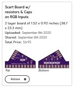
The Minigun Supergun 8-pin was designed specially to solve this problem - it has those resistors and capacitors built right onto the board and outputs 75Ohm R G and B by default
Similarly if your device is outputting TTL (line level) sync you need a resistor and cap on the sync line to attenuate the signal down to 75Oohm
The Minigun Supergun 8-pin was designed specially to solve this problem - it has those resistors and capacitors built right onto the board and outputs 75Ohm sync by default

Also, related question that you didn't ask - be aware that some SCART switchers use the +5v on Pin 8 for signalling

  1. is the COMPOSITE VIDEO (pin20 on scart) considered the SYNC pin on 8PIN connector? what about that TTL CSYNC shenanigans?
Yes, you want to send the CSYNC from the Minigun Supergun 8-pin to composite video (pin 20) on the SCART shell
There is no issue with TTL CSYNC on the Minigun Supergun 8-pin because it cannot generate TTL sync, only 75Ohm
  1. do i really have to ground all those pins? 5,9,13,17,18,21(case) togethere? i read somewhere that this is not necessary as long as the 18 and case-pin are grounded together?
Yes you do, the colors will be all funky if Red Ground (13) Green Ground (9) and Blue Ground (5) are not grounded
  1. can i ground audio-ground to the regular ground ? i dont intended to split the audio signal outside the scart so maybe i dont need that ground at all?
Yes you can, you may get some ground hum if your ground is dirty, but it will work fine. Again if there is no Audio ground on 4 there will be funky audio or no audio at all.
 
Last edited:
Hi another Minigun fan! I will do my best to help.


Lots of questions, answers in-line to keep it brief

Yes, that's the same one I used, works fine. Only thing to be aware of it that SCART pinouts are a bit inconsistent for plug/socket. Easier with SCART because it it keyed.

Sync is a massive subject
There is sync voltage.
This is either 75Ohm or TTL. 75Ohm is approx 1.5v Point to Point, TTL is 5v Point to Point.
In almost all use cases that we encounter at home you are going to want 75Ohm
on the Minigun Supergun 9 pin you can select 75Ohm or TTL with a Jumper at H4
on the Minigun Supergun 8 Pin you only have 75Ohm - so nice and easy

Then there is how the sync signal is generated
This is either seperate horizontal and vertical sync (RGBHV), or composite sync (RGBS)
For this application you want composite sync
The Minigun Supergun only outputs composite sync - so nice and easy there too

then there is the way sync is carried
This is either a composite sync signal on its own line (Composite Sync), or a composite sync signal carried on the composite video line (Composite Video), or a composite sync signal carried on the Green line of an RGB signal (Sync on Green or RGsB)
The Minigun supergug sends composite sync on it's own line - so that's nice and easy as well

To answer your question directly, there is no difference between TTL sync and CSYNC because they are not measuring on the same dimension.
We could say something like "what is the difference between TTL CSYNC and 75Ohm CSYNC" and the answer would be the voltage
Or we could ask something like "what is the difference between H+V sync and CSYNC" and the answer would be carried separately or combined on one line


This is the main reason that the MGSG 8-pin exists
Sync can be carried at TTL or at 75Ohm
The R G and B signals can be carried at 5ish volts (line level) or at .7ish volts (75Ohm)
Line level will destroy pretty much anything that isn't expecting it
So if your device is outputting line level RGB then you need a resistor and capacitor on each line to attenuate the signal down to 75Ohm
The Minigun Supergun 8-pin was designed specially to solve this problem - it has those resistors and capacitors built right onto the board and outputs 75Ohm R G and B by default
Similarly if your device is outputting TTL (line level) sync you need a resistor and cap on the sync line to attenuate the signal down to 75Oohm
The Minigun Supergun 8-pin was designed specially to solve this problem - it has those resistors and capacitors built right onto the board and outputs 75Ohm sync by default

Also, related question that you didn't ask - be aware that some SCART switchers use the +5v on Pin 8 for signalling


Yes, you want to send the CSYNC from the Minigun Supergun 8-pin to composite video (pin 20) on the SCART shell
There is no issue with TTL CSYNC on the Minigun Supergun 8-pin because it cannot generate TTL sync, only 75Ohm

Yes you do, the colors will be all funky if Red Ground (13) Green Ground (9) and Blue Ground (5) are not grounded

Yes you can, you may get some ground hum if your ground is dirty, but it will work fine. Again if there is no Audio ground on 4 there will be funky audio or no audio at all.
damn dude what a solid answer thanks, last night i spend some more time watching videos about rgb signal and sync and with that and your answer im starting to get a grab of this, i thought composite sync and sync on composite was the same :) boy oh boi was i wrong..

so correct me if im wrong:
1. if the 8pin supergun is giving only CSYNC (the 75ohm one) this is the 'safest syncs' available? i mean hooking it up to xrgb, ossc, anything else wont fry them?
2. i lost track in frank's topic of minigun, i know the 9pin version was created to have the 9 pin connector which has more easily available cables around. but i didnt knew there is a switch between TTL and CSYNC the H4 header on 8 pin version doesnt do this?
3. and still the question remains, is TTL SYNC somehow better than CSYNC?
 
Consumer CSync (75ohm) is 0.3v
TTL CSync is 5v
If you feed a 5v signal into a circuit expecting 0-0.3v, then problems occur.
In each case, the signal is the same, it’s just that 0-0.3v is more susceptible to noise than 0-5v which is why it is prevalent in higher grade applications.
 
so correct me if im wrong:
1. if the 8pin supergun is giving only CSYNC (the 75ohm one) this is the 'safest syncs' available? i mean hooking it up to xrgb, ossc, anything else wont fry them?
2. i lost track in frank's topic of minigun, i know the 9pin version was created to have the 9 pin connector which has more easily available cables around. but i didnt knew there is a switch between TTL and CSYNC the H4 header on 8 pin version doesnt do this?
3. and still the question remains, is TTL SYNC somehow better than CSYNC?
You're welcome - got covid at the moment, nothing to do but sit around all day writing about my hobby, you did me a favour giving me something to do.

1) Yes correct - this was the exact reason that Frank designed the 8-pin the way he did - for direct attachment to xrgb/ossc/etc without fear of damaging sensitive equipment.
2) H4 on the 9-pin version switches between TTL sync and 75 Ohm sync. H4 on the 8-pin version is a spare +5v header for a voltmeter or whatever.
3a) Again - we could answer the question "is TTL sync better than 75Ohm sync?" and the answer would be no - for home use 75Ohm sync is perfect, if you wanted to do genlock sync tricks with live cuts between multiple broadcast cameras then TTL would have a place, but it's unlikely we are running a TV studio here. The point is moot because the MGSG 8-pin only generates 75Ohm sync.
3b) or we could answer the question "is CSYNC better than H+V sync?" and the answer would be yes, almost none of the video equipment we use in this hobby can process H+V sync. The point is moot because the MGSG 8-pin only generates CSYNC
3c) or we could answer the question is "CSYNC better than Sync on Composite Video?" and the answer would be yes, sync on composite video does have the sync signal in there, but it also has a bunch of other info you don't need - depending on how your video equipment processes this it can cause unwanted visual artefacts (jailbars or etc) - but once again, the MSGS 8-pin cannot generate Sync on Composite Video, so the decision has already been made.

You've arrived at exactly the right place, and the device that you have suits your use-case perfectly - I think you can proceed with confidence.

You already know this, but just in case someone else finds this thread later
Retrogaming cables sell a purpose built 8-pin cable that works perfectly with the MGSG 8-pin
https://www.retrogamingcables.co.uk...-CDi-Colecovision-Intellivision-Panasonic-3DO
And for our friends on the other side of The Atlantic Retro Access have a similar product
https://retro-access.com/collections/other/products/8-pin-male-mini-din-to-male-rgb-scart
https://retro-access.com/collection...aflex-8-pin-mini-din-rgb-scart-cable-for-mods

Looking forward to seeing how the cable making goes - I did investigate buying an injection moulding machine to do my own over moulding, but prices started in the tens of thousands. I think a 3D printed mould with a pour of flexible resin for strain relief, then a pour of hard resin for wear resistance is probably as good as I'll ever get in my home workshop, and then I got bored and gave up. I'd love to know where you land up with this!
 
  • Like
Reactions: Pap
thanks i think you answered ALL my concerns. yeah i have a bunch of cables from retrogamingcables, but sadly since they are out of EU the shipping +taxes+duty payments (yeah in my country i pay for processng duty forms that there is no duty to be paid :D) buying from them is getting very expensive
and since im doing fine with soldering and making cables and have the tools i will give it a go with doing my own.
 
You're welcome - got covid at the moment, nothing to do but sit around all day writing about my hobby, you did me a favour giving me something to do.

1) Yes correct - this was the exact reason that Frank designed the 8-pin the way he did - for direct attachment to xrgb/ossc/etc without fear of damaging sensitive equipment.
2) H4 on the 9-pin version switches between TTL sync and 75 Ohm sync. H4 on the 8-pin version is a spare +5v header for a voltmeter or whatever.
3a) Again - we could answer the question "is TTL sync better than 75Ohm sync?" and the answer would be no - for home use 75Ohm sync is perfect, if you wanted to do genlock sync tricks with live cuts between multiple broadcast cameras then TTL would have a place, but it's unlikely we are running a TV studio here. The point is moot because the MGSG 8-pin only generates 75Ohm sync.
3b) or we could answer the question "is CSYNC better than H+V sync?" and the answer would be yes, almost none of the video equipment we use in this hobby can process H+V sync. The point is moot because the MGSG 8-pin only generates CSYNC
3c) or we could answer the question is "CSYNC better than Sync on Composite Video?" and the answer would be yes, sync on composite video does have the sync signal in there, but it also has a bunch of other info you don't need - depending on how your video equipment processes this it can cause unwanted visual artefacts (jailbars or etc) - but once again, the MSGS 8-pin cannot generate Sync on Composite Video, so the decision has already been made.

You've arrived at exactly the right place, and the device that you have suits your use-case perfectly - I think you can proceed with confidence.

You already know this, but just in case someone else finds this thread later
Retrogaming cables sell a purpose built 8-pin cable that works perfectly with the MGSG 8-pin
https://www.retrogamingcables.co.uk...-CDi-Colecovision-Intellivision-Panasonic-3DO
And for our friends on the other side of The Atlantic Retro Access have a similar product
https://retro-access.com/collections/other/products/8-pin-male-mini-din-to-male-rgb-scart
https://retro-access.com/collection...aflex-8-pin-mini-din-rgb-scart-cable-for-mods

Looking forward to seeing how the cable making goes - I did investigate buying an injection moulding machine to do my own over moulding, but prices started in the tens of thousands. I think a 3D printed mould with a pour of flexible resin for strain relief, then a pour of hard resin for wear resistance is probably as good as I'll ever get in my home workshop, and then I got bored and gave up. I'd love to know where you land up with this!
Actually 1 more question, found this image of pinout:
1665926177878.png


and i noticed the 8pin socket 4th pin ground is connected to SCART 5pin and then the shield ground is connected to the rest of ground on scart, this has put me into questioning mode, do i have to put the 4th pin GND separate from rest of GND on scart?
 
I'm glad you asked all these SCART questions. I've been wondering them all too. I've made and repaired SCART stuff but I don't know anything about the"why", so this stuff is really confusing for me too
 
Actually 1 more question, found this image of pinout:
1665926177878.png


and i noticed the 8pin socket 4th pin ground is connected to SCART 5pin and then the shield ground is connected to the rest of ground on scart, this has put me into questioning mode, do i have to put the 4th pin GND separate from rest of GND on scart?
That one is a bit different from the first diagram, if I was going to choose I would build from the first diagram you posted

Pin 5 of the scart shell is “blue ground” in the scart spec (identical to red ground and green ground). So In this diagram blue is getting ground from the console pin, and red and green are getting ground from the shell/shield. I can’t think of a single good reason to do this.

I guess there is an argument to keep audio ground (scart pin 4) seperate from video ground, but that’s not what is being shown in that second diagram.

So yeah, hopefully someone more experienced than me can add additional info, but at this stage I would stick to the original diagram and ground scart pin 5 (blue ground) the same way as all the others
 
Back
Top