
Resurrecting the 32/64MBIT flash project and 8/16 bit addressing.

Screenshot 2024-10-18 at 12.58.25 PM.png
Screenshot 2024-10-18 at 12.58.39 PM.png


https://www.mvs-scans.com/misc/toshiba-64mbit-adapter-master-ack2.zip

Just to be clear, they need to be 74HCT244 and not 74HC244
Would I be able to use the current form of the adapter here to replace the 64-mbit chips in a SEGA Model 3 rom board like the Spikeouts or is that still unconfirmed at this point?
Or would I need to wait for and use the Tailsnic Retroworks variation of the board whenever that becomes available, assuming that would even work with a Sega Mdoel 3 rom board as opposed to the Neo-Geo MVS romboards/cartridge pcbs it's primarily being made for?
 
The 64 will work.
You have to hand solder the chip on.
You have to have 1 each pcb for 1 each eprom.
The new adapter is mainly neo geo.
I might play with it to see if it works on model 3 but not soon.
Keep in mind most model 3 using 64mb are encrypted.
 
The old version of that PCB worked on my Spikeout (the version that used 5x HC244), so this should work too
Thanks. Do you remember what 48 pin TSOP rom chip did you use with the PCB that worked with Spikeout? I think I saw the MX29LV320EBTI chip mentioned as a valid chip to use with the adapter?

Should I be setting the adapter to work in Word mode or Byte mode for use in a Model 3 rom board?
 
Thanks. Do you remember what 48 pin TSOP rom chip did you use with the PCB that worked with Spikeout? I think I saw the MX29LV320EBTI chip mentioned as a valid chip to use with the adapter?

Should I be setting the adapter to work in Word mode or Byte mode for use in a Model 3 rom board?
Spikeout uses a lot of 64mbit DIP42 format roms, so you need S29GL064.

For 32mbit DIP42 roms use 27c322.
 
Spikeout uses a lot of 64mbit DIP42 format roms, so you need S29GL064.

For 32mbit DIP42 roms use 27c322.
Thanks.

The 27c322 seems to be word-only according to a quick pdf check, so I assume that the toshiba adapter would have to be set to word-mode as well for Spikeout?

According to Digikey (https://www.digikey.com/short/8f0mh51n) there's at least 54 different variations of 48TSOP S29GL064 chips available from multiple companies, not sure if you remember the specific model you were using and that I should be using for Spikeout

Would it work with only the chips with both byte and word read support or should I use the version with word-mode only support?
 
I don't know what is the problem of choosing the roms.

27c322 are perfectly flasheable and eraseable with UV, so for 32mbit (4MB) are good, but only for 16bit WORD mode.
About the 64mbit (8MB) tsop48 flash roms, I use S29GL064N90TFI04, and for those you can use BYTE mode.
 
maybe a day.... we will see Tailsnic Retroworks adapter :whistling:
Believe me, I'm with other personal projects that share the same system in these adapters. When I archieve the perfection on them, I can move the knowing to this adapter. If you want me to make it really good, keep waiting.
 
I have a SF EX2 Plus board that has a failed 64mbit mask ROM (looks to be a Sharp LH5364000) - would this board (or something similar) work as a replacement board considering the original IC make/model type isn't available? I know this solution isn't ZN-2 specific, but keen to see if it could be modified to be used in a ZN-2 board
 
Last edited:
Hi. Sorry for all the waiting. Here I attach the 2 gerbers you need for universal conversions / repairs on MVS boards

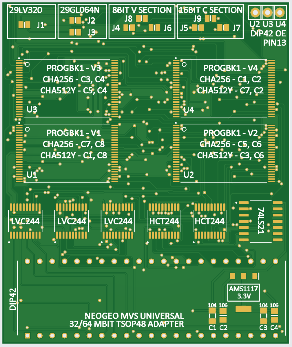
UNIVERSAL V-SOUND AND C-GRAPHICS BOARD FOR PROGBK1, CHA256, CHA256B AND CHA512Y BOARDS. CORRECT GERBER VERSION HERE: LINK
1787069637137.png


8BIT V SECTION IS ONLY FOR 29LV320, SOUND SECTION
16BIT C SECTION ARE FOR BOTH 29LV320 AND 29GL064N, GRAPHICS SECTIONS. 64MBITS ARE ONLY ALLOWED IN CHA512Y BOARDS.


JOIN ALL THE JUMPERS OF EACH GROUP OF CONFIGURATION YOU WANT TO USE

- 29LV320 OR 29GL064N

- 8BIT V SECTION OR 16BIT C SECTION


The materials to use:

2.54mm 2x21 male pins
3x LVC244A
2x HCT244
1x 74LS21
1x AMS1117 3.3V
2x 10⁴ 0805 capacitor
2x 10⁶ 0805 capacitor
4x 29LV320 or 4x 29GL064N, or the quantity you need for the game
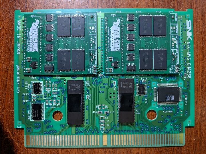
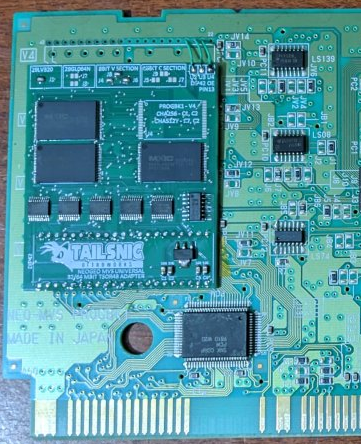
Set the jumpers for the zone you are going to use the board. Use the same positions as my photos, and follow the indications of the silkscreens. OE pins must be connected using PIN13 of each rom. U1 ROM PIN13 IS ALWAYS CONNECTED BY DEFAULT WITHOUT ANY CABLE.
1787070122891.png


1787070408517.png


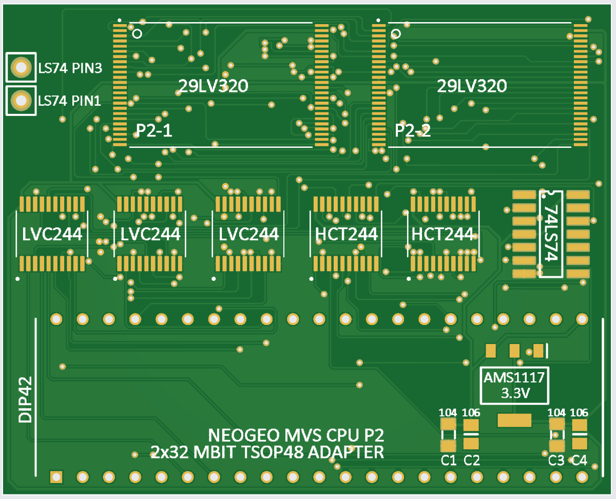
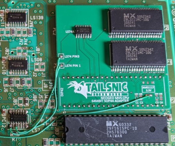
PROGBK1 P2 ROM BANK EXPANSION BOARD. TESTED IN GAMES LIKE SAMURAI SHODOWN V SPECIAL, SNK VS CAPCOM CHAOS AND THE KING OF FIGHTERS 2003.

1787069708580.png


LS74 PIN3 AND LS74 PIN1 POINTS ARE FOR CATCHING SIGNALS REQUIRED BY THIS ADD-ON, THAT ARE IN THE PROGBK1 BOARD. USE THE LAST PHOTO AS GUIDE (IS THE PREVIOUS PCB VERSION). PROGBK1 BOARD HAS TO BE PREPARED WITH ITS ORIGINAL JUMPERS DISTRIBUTION FOR BIGGEST 1MB+4MB CPU GAMES.

FOR PREPARING THE P1, P2-1 AND P2-2 ROMS USING VORTEX ROMS AS REFERENCE IN GAMES WITH +5MB ON P1+P2 ROM:
- FIRST 1MB IS P1
- NEXT 4MB IS P2-1
- REST OF MB IS P2-2


The materials to use:

2.54mm 2x21 male pins
3x LVC244A
2x HCT244
1x 74LS74
1x AMS1117 3.3V
2x 10⁴ 0805 capacitor
2x 10⁶ 0805 capacitor
2x 29LV320

1787070534789.png
 

Attachments

Last edited:
Hi. Sorry for all the waiting. Here I attach the 2 gerbers you need for universal conversions / repairs on MVS boards

UNIVERSAL V-SOUND AND C-GRAPHICS BOARD FOR PROGBK1, CHA256, CHA256B AND CHA512Y BOARDS.

1787069637137.png


8BIT V SECTION IS ONLY FOR 29LV320, SOUND SECTION
16BIT C SECTION ARE FOR BOTH 29LV320 AND 29GL064N, GRAPHICS SECTIONS. 64MBITS ARE ONLY ALLOWED IN CHA512Y BOARDS.


JOIN ALL THE JUMPERS OF EACH GROUP OF CONFIGURATION YOU WANT TO USE

- 29LV320 OR 29GL064N

- 8BIT V SECTION OR 16BIT C SECTION


The materials to use:

2.54mm 2x21 male pins
3x LVC244A
2x HCT244
1x 74LS21
1x AMS1117 3.3V
2x 10⁴ 0805 capacitor
2x 10⁶ 0805 capacitor
4x 29LV320 or 4x 29GL064N, or the quantity you need for the game
Set the jumpers for the zone you are going to use the board. Use the same positions as my photos, and follow the indications of the silkscreens. OE pins must be connected using PIN13 of each rom. U1 ROM PIN13 IS ALWAYS CONNECTED BY DEFAULT WITHOUT ANY CABLE.


1787070122891.png


1787070408517.png


PROGBK1 P2 ROM BANK EXPANSION BOARD. TESTED IN GAMES LIKE SAMURAI SHODOWN V SPECIAL, SNK VS CAPCOM CHAOS AND THE KING OF FIGHTERS 2003.


1787069708580.png


LS74 PIN3 AND LS74 PIN1 POINTS ARE FOR CATCHING SIGNALS REQUIRED BY THIS ADD-ON, THAT ARE IN THE PROGBK1 BOARD. USE THE LAST PHOTO AS GUIDE (IS THE PREVIOUS PCB VERSION). PROGBK1 BOARD HAS TO BE PREPARED WITH ITS ORIGINAL JUMPERS DISTRIBUTION FOR BIGGEST 1MB+4MB CPU GAMES.

FOR PREPARING THE P1, P2-1 AND P2-2 ROMS USING VORTEX ROMS AS REFERENCE IN GAMES WITH +5MB ON P1+P2 ROM:
- FIRST 1MB IS P1
- NEXT 4MB IS P2-1
- REST OF MB IS P2-2


The materials to use:

2.54mm 2x21 male pins
3x LVC244A
2x HCT244
1x 74LS74
1x AMS1117 3.3V
2x 10⁴ 0805 capacitor
2x 10⁶ 0805 capacitor
2x 29LV320


1787070534789.png
Can we have also assembly file ? so we can order already with component solder on ?
I mean Pick&Place and Bom file.
Thanks for sharing.

2.54mm 2x21 male pins
3x LVC244A
2x HCT244
1x 74LS74
1x AMS1117 3.3V
2x 10⁴ 0805 capacitor
2x 10⁶ 0805 capacitor
 
Last edited:
Is good to know I have chosen well for publishing these specific free revisions. Thanks
Now I think we've covered every issue on this topic, between bankswitching workarounds, new BK1 PCBs, and adapters, we can consider the case closed and 100% covered. Also good for anyone who wants to make their own copies of Zintrick and CR2 or (for what ADK Word is worth)
I'm happy to see many thinking heads at work.

Someone should index the solutions on this forum and post them as sticky threads.
 
Back
Top