
You are using an out of date browser. It may not display this or other websites correctly.
You should upgrade or use an alternative browser.
You should upgrade or use an alternative browser.
MITSU Wait List: Batman Forever sound pcb repro
- Thread starter Mitsurugi-w
- Start date
RepairGuy95
Champion
Seconded.
Also, Is he okay?
Also, Is he okay?


No one has heard from him in almost two years. Don't expect the adapter unless someone else creates one.

mathewbeall
Enlightened
mathewbeall
Enlightened
I am willing to give a go at trying to recreate this - if no one else has.
RepairGuy95
Champion
Please do. I think the project is otherwise dead and it would make it so much more convenient.

Orakelschaf
Professional
@mathewbeall : go ahead! - If you don't: i can have a look at it in a couple of days, but currently busy. No promises 
I had a look at the existing graphics and tried to simple trace the copper, but either the image renderings are not complete or the design was not fully traced.
I can give it a try in a couple of days, but currently busy as hell. I am not sure what some of the stuff does:
- the line level volume: - Which potentiometer is required?
- What is the difference between "spk" and "aud" on the jamma pin headers. why are there 3 pins?
- What does the button remap exactly do?
- What does the S + - below the voltmeter do? is this voltage? is this speaker? Why is it 3 pins?
- does anybody have a list of the used pin header (name/size)?
- it is not that difficult to create, wonder if all that stuff gets used
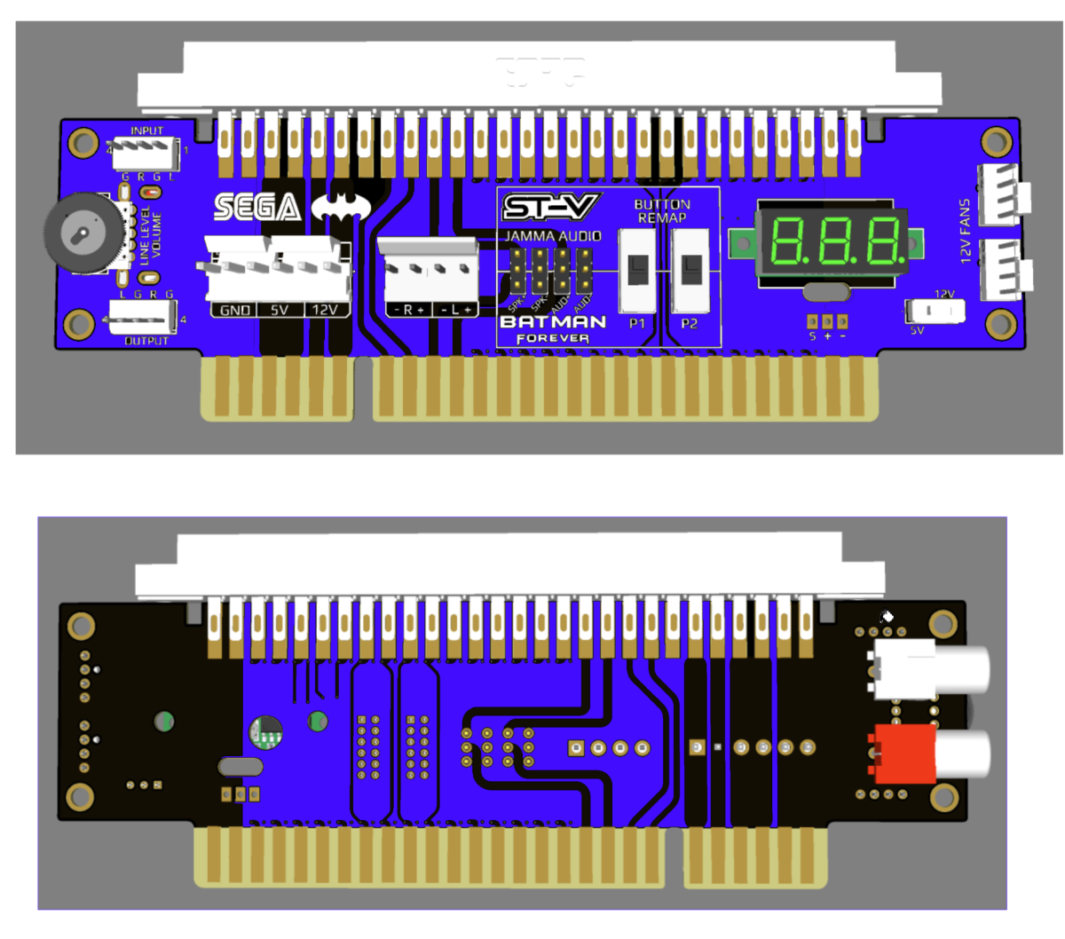
I had a look at the existing graphics and tried to simple trace the copper, but either the image renderings are not complete or the design was not fully traced.
I can give it a try in a couple of days, but currently busy as hell. I am not sure what some of the stuff does:
- the line level volume: - Which potentiometer is required?
- What is the difference between "spk" and "aud" on the jamma pin headers. why are there 3 pins?
- What does the button remap exactly do?
- What does the S + - below the voltmeter do? is this voltage? is this speaker? Why is it 3 pins?
- does anybody have a list of the used pin header (name/size)?
- it is not that difficult to create, wonder if all that stuff gets used
RepairGuy95
Champion
I think it kind of turned into a universal adapter if I remember so you could leave it plugged into the multi and bypass it via jumpers if not playing Batman.
I am not sure if it is all necessary. I think the idea was to bypass jamma and use the amp for all games.
I am not sure if it is all necessary. I think the idea was to bypass jamma and use the amp for all games.
Not sure if it’s also something @Big_P Big_p would look at? (Sorry for tagging, just seen you dabble in some board making activities recently)
mathewbeall
Enlightened
I was willing to give it the college try and use AI to help me , but if someone REALLY knows what they are doing - they would likely be able to do it quicker! If I don't hear anything in a day, I will start working on it to see what I can figure out!
mathewbeall
Enlightened
Looking at this in more detail....
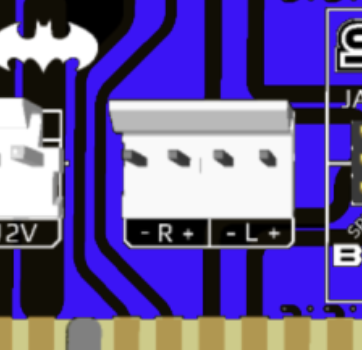
This brings the amplified R and L audio signals back to the JAMMA edge - can we tell how its mixing the signals down to mono? And where is this connector on the mitsu repro board? I can't seem to tell on the pictures, and my board is in storage so I can't eyeball it.
 ≈
≈
and these jumpers are basically - all at the bottom means that the audio to the JAMMA edge comes from the middle 4 pin JST header (from the audio board) and if the jmpers are up to the ST-V graphic, they just traverse the JAMMA path unimpeded?
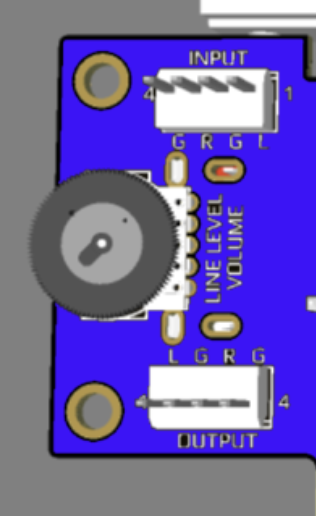
This part seems pretty simple - if you have an amp in your cabinet, but no line level control - this takes the line level input from the audio board, runs through the POT (not sure what value this is) and then output to your amplifer.
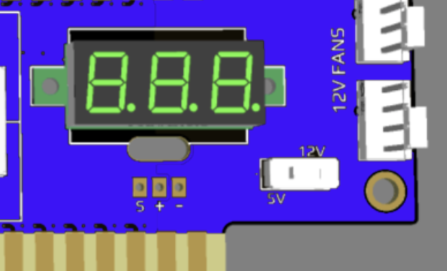
button remap is clear of what its doing, as well as the 12v fan headers and the 12v/5v display.
What isn't clear is that the small headers are beneath the voltage display (S + -)
Matt
This brings the amplified R and L audio signals back to the JAMMA edge - can we tell how its mixing the signals down to mono? And where is this connector on the mitsu repro board? I can't seem to tell on the pictures, and my board is in storage so I can't eyeball it.
and these jumpers are basically - all at the bottom means that the audio to the JAMMA edge comes from the middle 4 pin JST header (from the audio board) and if the jmpers are up to the ST-V graphic, they just traverse the JAMMA path unimpeded?
This part seems pretty simple - if you have an amp in your cabinet, but no line level control - this takes the line level input from the audio board, runs through the POT (not sure what value this is) and then output to your amplifer.
button remap is clear of what its doing, as well as the 12v fan headers and the 12v/5v display.
What isn't clear is that the small headers are beneath the voltage display (S + -)
Matt
Orakelschaf
Professional
> and these jumpers are basically
those are jumpers, got it! - thought it was another connection point.
> button remap is clear of what its doing
so what does it do?
> can we tell how its mixing the signals down to mono
there is no chip on that board which does that. Maybe just connection L+R? - I see no traces on that pcb, maybe logic was not implemented?
It is a really simple PCB, we all should be able to figure it out.
those are jumpers, got it! - thought it was another connection point.
> button remap is clear of what its doing
so what does it do?
> can we tell how its mixing the signals down to mono
there is no chip on that board which does that. Maybe just connection L+R? - I see no traces on that pcb, maybe logic was not implemented?
It is a really simple PCB, we all should be able to figure it out.

What does the S + - below the voltmeter do? is this voltage? is this speaker? Why is it 3 pins?
It's for the voltage meter. It's 3 pin, because one is for power (+), one for common ground (-) and one for the voltage you're measuring (S; selectable with the little slide switch).
mathewbeall
Enlightened
this post earlier in the thread is about the remap.> and these jumpers are basically
those are jumpers, got it! - thought it was another connection point.
> button remap is clear of what its doing
so what does it do?
> can we tell how its mixing the signals down to mono
there is no chip on that board which does that. Maybe just connection L+R? - I see no traces on that pcb, maybe logic was not implemented?
It is a really simple PCB, we all should be able to figure it out.

@Derick2k these JAMMA edge board you're making, you'll want to do a button remap on them too. For some stupid reason button 1 is mapped to 2, 2 is mapped to 3 and 3 is mapped to 4 
if you look at pages 23 and 24 of the manual they show that for batman "button A" is not used :-/
if you look at pages 23 and 24 of the manual they show that for batman "button A" is not used :-/


dillingerradio
Professional
Hello!
I'm interested in an audio repro board, if you've still got some.
I'm interested in an audio repro board, if you've still got some.
Ill make another batch later this year. Gotta get a few other preorders shipped.
RepairGuy95
Champion
Any progress on the add on board?
Not unless someone new designs one. Derick2k seems to have left the hobby.
RepairGuy95
Champion