
You are using an out of date browser. It may not display this or other websites correctly.
You should upgrade or use an alternative browser.
You should upgrade or use an alternative browser.
MITSU Wait List: Batman Forever sound pcb repro
- Thread starter Mitsurugi-w
- Start date

mathewbeall
Enlightened
Hmmm - well then maybe its the board options I chose (ENIG, gold fingers) - it said they would start building it on the 24th.Awesome work! I believe that JLCPCB will not close during chinese new year this time.

I might recommend some radiuses in the corners, especially on the JAMMA edge. even a 0.5mm radius makes a huge difference.
Also confirm that the total width and other dimensions are in-line with the official JAMMA Spec:
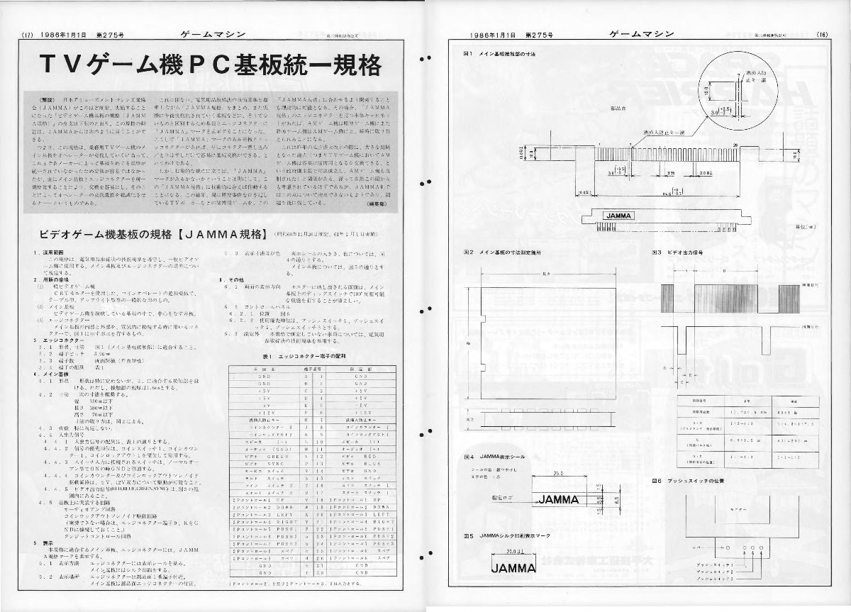
EDIT: a better more readable pic:

Also confirm that the total width and other dimensions are in-line with the official JAMMA Spec:
EDIT: a better more readable pic:
mathewbeall
Enlightened
When you say a radius - do you mean to just round the JAMMA gold fingers a little bit?I might recommend some radiuses in the corners, especially on the JAMMA edge. even a 0.5mm radius makes a huge difference.
Also confirm that the total width and other dimensions are in-line with the official JAMMA Spec:
EDIT: a better more readable pic:
no I mean the pcb corners should be roundedWhen you say a radius - do you mean to just round the JAMMA gold fingers a little bit?
it helps with insertion and actually make the PCB less prone to chipping and cracking

im in for a sound board and the adapter board

GhaleonUnlimited
Professional
Following the progress of the thread, is the issue that basically that the Batman Forever sound module cannot be reproduced again because the main designer is gone ?
Or are you guys working to recreate something else with this ?
Thanks either way for all you guys do for the hobby
Or are you guys working to recreate something else with this ?
Thanks either way for all you guys do for the hobby
mathewbeall
Enlightened
@Mitsurugi-w has already recreated the sound board (see first post) - what I am doing is essentially a helper board that routes power to the sound board from the JAMMA edge, and then audio back for folks using this in a JAMMA cabinet. Along with (hopefully) some nice to haves like 12V fan headers so that when someone makes a nice enclosure for this, cooling won't be an issue.
mathewbeall
Enlightened
and to be clear - I am just trying to recreate what a previous Ap member had already created. So this isn't really my idea at all - I am just trying to make it a reality
mathewbeall
Enlightened
Quick update - I got the prototype boards - I should get time this weekend to get it wired up and see if basic functionality works - some of the pieces I ordered don’t fit the footprint and I’ll need to play around with the a lot of finishing touches like silkscreen etc - but baby steps!
mathewbeall
Enlightened
I tested it in "passthrough mode" and hooked up the voltmeter, just to make sure everything like normal worked there. I still don't have the button remap switches, so I can't actually go in and play anything since the buttons all go through those switches and I don't want to hook up a bunch of temp wires.
BUT - at least audio/video/power all came through - so thats great!
Now I am going to work on hooking up the power from the helper board over to the audio amp board, and the amplified audio signals back over to the helper board and see if that is all working. Then I can work on testing the buttons later this week (hopefully) when I get the button remap switches, as well as testing the seperate line-level audio input stage.
edit: sigh - i ordered the wrong crimp connectors, so will have to wait for those to come in.
BUT - at least audio/video/power all came through - so thats great!
Now I am going to work on hooking up the power from the helper board over to the audio amp board, and the amplified audio signals back over to the helper board and see if that is all working. Then I can work on testing the buttons later this week (hopefully) when I get the button remap switches, as well as testing the seperate line-level audio input stage.
edit: sigh - i ordered the wrong crimp connectors, so will have to wait for those to come in.
Last edited:

Cheers!BUT - at least audio/video/power all came through - so thats great!
Awesome! Please keep us updated.Now I am going to work on hooking up the power from the helper board over to the audio amp board, and the amplified audio signals back over to the helper board and see if that is all working. Then I can work on testing the buttons later this week (hopefully) when I get the button remap switches, as well as testing the seperate line-level audio input stage.
mathewbeall
Enlightened
While I am waiting on the 4PDT switches to arrive - I went in and modified some parts and did some silkscreen work. We will see how everythign goes together, and assuming the actual audio part works, much closer to a production board. I am not sure why Derrick2k did 4 sets of jumpers to switch the audio back and forth between JAMMA and Batman - so I just used another 4PDT switch here.
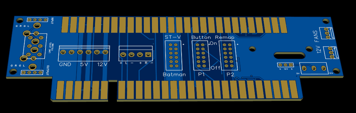
mathewbeall
Enlightened
Ok - used some simpler RCA jacks with less posts and this allows me to use a better molex connector for the line level input and output - here is what likely is the final version of the next test run of these boards. I should get the switches in a couple of days so I can test those, and darn it if digikey STILL hasn't shipped my darn crimp connectors - they seem really backed up which is unusual for them. Placed the order on Sunday and still hasn't shipped.
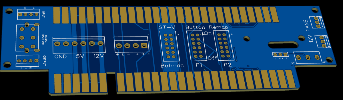
Last edited:
mathewbeall
Enlightened
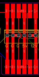
Sorry for spamming this so much - but I just made one more change - curious what all of you who are vastly more experienced than I am at this. I want to make the wiring easier and not have to deal with a spliced connector (since the power amp board just needs 1 5v, 3Ground and 2 12V), so I adjusted the helper board. By doing that, it takes away essentially (2 (top and bottom)) 2.0mm 5V traces and replaces it with a .5mm trace. So the total trace width available for the 5V is 2mm (top and bottom) and .5mm (top and bottom) for a total of 5mm trace width to carry the 5v current. With 2 oz copper, according to claude it says that can carry about 8amp of current, and it figures that the current draw on the ST-V and amp board (on the 5v rail) doesn't go above 6.
Any red flags? Am I cutting it too close?
Any red flags? Am I cutting it too close?
RepairGuy95
Champion
I see no spam here. I see cool progress.

Those pads you have on the edge connector look too wide. As someone who has misaligned a jamma connector once and burned down a whole cab harness, I would double check that.
Measuring the edge connector on a CPS2 the edge to edge width on a pad is 2.16mm and the gap in between is 1.80mm for a pin spacing of 3.96.
If you're on a ArcadeOtaku, here's a very recent example of an edge connector causing problems:
https://forum.arcadeotaku.com/viewtopic.php?p=577696#p577696
Measuring the edge connector on a CPS2 the edge to edge width on a pad is 2.16mm and the gap in between is 1.80mm for a pin spacing of 3.96.
If you're on a ArcadeOtaku, here's a very recent example of an edge connector causing problems:
https://forum.arcadeotaku.com/viewtopic.php?p=577696#p577696

HardAzRockz
Professional
Awesome work. Is this going to be open source?Sorry for spamming this so much - but I just made one more change - curious what all of you who are vastly more experienced than I am at this. I want to make the wiring easier and not have to deal with a spliced connector (since the power amp board just needs 1 5v, 3Ground and 2 12V), so I adjusted the helper board. By doing that, it takes away essentially (2 (top and bottom)) 2.0mm 5V traces and replaces it with a .5mm trace. So the total trace width available for the 5V is 2mm (top and bottom) and .5mm (top and bottom) for a total of 5mm trace width to carry the 5v current. With 2 oz copper, according to claude it says that can carry about 8amp of current, and it figures that the current draw on the ST-V and amp board (on the 5v rail) doesn't go above 6.
Any red flags? Am I cutting it too close?

If you're using KiCad, it's fairly straightforward to create a JAMMA footprint with the correct spacing, once you know how.
In your footprint, create one rectangular pad, roughly 2.1-2.3 mm wide and about 8-10mm high. Then select it, right-click, Create from Selection, Create Array... Set the horizontal spacing to 3.96mm and set the horizontal count to 28 and the vertical count to 1.
That then creates an array of pads spaced correctly. Duplicate those so they're on both the front and back copper layers for 56. If it's a harness-facing, remove pads 7 & H for the key notch.
I will try and make a reusable library although KiCad doesn't make it the easiest.
In your footprint, create one rectangular pad, roughly 2.1-2.3 mm wide and about 8-10mm high. Then select it, right-click, Create from Selection, Create Array... Set the horizontal spacing to 3.96mm and set the horizontal count to 28 and the vertical count to 1.
That then creates an array of pads spaced correctly. Duplicate those so they're on both the front and back copper layers for 56. If it's a harness-facing, remove pads 7 & H for the key notch.
I will try and make a reusable library although KiCad doesn't make it the easiest.
the 2oz of copper is fine but you're also forcing all of this through the through-holes which can be a bottleneck.With 2 oz copper, according to claude it says that can carry about 8amp of current, and it figures that the current draw on the ST-V and amp board (on the 5v rail) doesn't go above 6.
Any red flags? Am I cutting it too close?
I'd recommending adding copper in the green areas:
it probably couldn't hurt to widen your -5V as much as you can.