What's new

How to Net-boot NAOMI/Tri-Force/Chihiro Using Pi-Force Tools

Yea I made mine as well, I might have extra parts to make another... But they are all packed away in storage (who knows when I'll dig 'em out).
Oh I just remember @Mitsurugi-w had some for sale at one point, I'd ask him.
 
Last edited by a moderator:
Thanks guys, I'm digging throw my spare electronic stuff to see if i find one to cut open ^^ .

Jassin always to the rescue haha :thumbup:
 
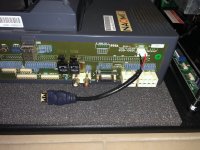
I actually found a 2.0 usb female end and made the connector in 2 mins :D
 

Attachments

  • E05C271E-1243-4201-BC40-B73C8F4985AC.jpeg
    E05C271E-1243-4201-BC40-B73C8F4985AC.jpeg
    285.8 KB · Views: 92
Just be carefull. Not all usb cables have thick enough wires to handle the 2 Amps peak current the pi needs.
The Pi 1 it's usb ports were extremely sensitive to under voltage. When the pi only got 4.7 instead of 5V, some usb devices didn't work anymore.
If you look at a traditional pi power adapter you will see that only 2 thicker wires go to the micro usb plug. The adapter is also set to 5.1V to compensate for cable losses. Specially cheap chinese usb to micro usb cables often have very thin wires.

I am not saying you will experience issues. Just saying if you have some, you might check the pi voltage on it's gpio connector.
 
Looking really good @KingSopz Naomi is one of my favorite arcade systems, so many good games!

Don't forget to grab some of the patched/unlocked binarys like MvC2 and Power Stone 2.
 
That looks about right!!! Get ready for some fun :)
Cant wait :)
Looking really good @KingSopz Naomi is one of my favorite arcade systems, so many good games!

Don't forget to grab some of the patched/unlocked binarys like MvC2 and Power Stone 2.
thanks bro! Im definitely checking those out :), I'm just waiting on my SD card, multi region bios and the power cable for the naomi sun psu to arrive. Should be here any day now :S
 
Ill hit up storage this Sunday man... The only issue you'll have with using the image I can generate is you'll need to use the same size SD card (or use a larger one then resize the partition after the transfer).
 
Ill hit up storage this Sunday man... The only issue you'll have with using the image I can generate is you'll need to use the same size SD card (or use a larger one then resize the partition after the transfer).
na bro im not gonna make you go throw all that lol is cool ill get it done from scratch, i got the instructions on the piforce the only issue im having is the part to make the raspberry pi work with the lcd, im sure its easy and im over thinking but i cant seem to understand the steps because im seeing you need to run the python script but idk how. I have no knowledge on raspberry pi :S , if someone here can give me a step by step on what to do after assembling the lcd that would be a great help because the adafruit instruction seem to be giving me extra steps to do that i know i don't need.
 
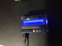
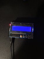
I installed piforce and this is what i get, any suggestions? ?(
Im running a Raspberry Pi 2 on the adafruit 16x2 LCD
 

Attachments

  • 269A47E1-AF83-4283-B96E-ED3D5EC7177E.jpeg
    269A47E1-AF83-4283-B96E-ED3D5EC7177E.jpeg
    214.9 KB · Views: 78
  • B8EAD44C-6233-4ACC-8B3E-23DA11988B88.jpeg
    B8EAD44C-6233-4ACC-8B3E-23DA11988B88.jpeg
    178.4 KB · Views: 86
Last edited:
This is typically what those displays are showing if they don't receive any data from the raspberry pi.
Maybe you should try the image they prepared for you first to see if it works.
It can prove all hardware is working as expected. Next, you can experiment with creating your own image.

I have no idea how the adafruit display is interfaced (IIC, SPI, 4 bit parallel?)
Depending upon the method you might need to run the raspi-config program and enable that interface.
I am pretty sure adafruit has tutorials about what needs to be done to test the display assembly.

You should at least learn a bit of linux basics like how you can ssh into the raspberry pi to control it.
Connecting a display, keyboard and mouse is another way you can control it.
The display will show you the pi boot sequence. It can pinpoint problems during booting.
 
thanks for all the suggestions guys, I notice i solder the chip the wrong way X/ , i will rotate it tonight and hopefully that was my issue. Ill post results.
 

Attachments

  • D5D004DF-B415-4F6D-B065-BEE5603B0580.jpeg
    D5D004DF-B415-4F6D-B065-BEE5603B0580.jpeg
    169.4 KB · Views: 79
If you are very lucky, the chip might still work, but it's probably best to get a new one.
Yea I was thinking the same... Also its going to be really hard to desolder that cleanly using only braid/iron.
A faster way would be to snip all the feet off the chip, and then heat/pull each foot out of the thru-hole separately (this of course would totally destroy the chip package, so you would need another).
 
Back
Top