MITSU Wait List: Batman Forever sound pcb repro

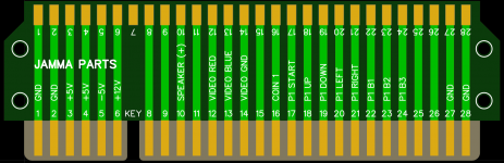
Those pads you have on the edge connector look too wide. As someone who has misaligned a jamma connector once and burned down a whole cab harness, I would double check that.

Measuring the edge connector on a CPS2 the edge to edge width on a pad is 2.16mm and the gap in between is 1.80mm for a pin spacing of 3.96.

If you're on a ArcadeOtaku, here's a very recent example of an edge connector causing problems:

https://forum.arcadeotaku.com/viewtopic.php?p=577696#p577696

I will check on the width - I do think they are wider than 2.16mm.

Thanks!
 
the 2oz of copper is fine but you're also forcing all of this through the through-holes which can be a bottleneck.
I'd recommending adding copper in the green areas:
traces.jpg

it probably couldn't hurt to widen your -5V as much as you can.
This was before I did some copper ground pours, so that takes care of the left, I will look and see to do a copper run surrounding the 5V there, good Idea on that. And over on the 12V side.

Why make the -5 larger? I was under the impression that the ST-V didn't even use the -5v line?
 
If you're using KiCad, it's fairly straightforward to create a JAMMA footprint with the correct spacing, once you know how.

In your footprint, create one rectangular pad, roughly 2.1-2.3 mm wide and about 8-10mm high. Then select it, right-click, Create from Selection, Create Array... Set the horizontal spacing to 3.96mm and set the horizontal count to 28 and the vertical count to 1.

That then creates an array of pads spaced correctly. Duplicate those so they're on both the front and back copper layers for 56. If it's a harness-facing, remove pads 7 & H for the key notch.

I will try and make a reusable library although KiCad doesn't make it the easiest.
I am using EasyEDA Pro (desktop version).

I actually did get that footprint from a library and didn't create it myself. But I will look to make these adjustments!
 
What is the consensus on pad width for the goldfingers? I am seeing all sorts of information out on the interweb. 2.3m to 2.5mm? I know @nem said 2.16mm.
the official JAMMA spec that I posted for you earlier says 2.0mm or wider.

This is the kind of thing where I wouldn't trust the opinions on the internet and rather use logic and measurements to work out.

measure the ST-V pads and see how wide they are. measure a few other games to see if their similar.
find your loosest jamma connector and your most narrow JAMMA edge and measure how much it can shift left to right, then make sure the pads are narrow enough to not create a jump.

find your JAMMA connector with the fattest contacts and measure how wide they are

^all of those are more valuable sources of information an opinions on the internet.
 
I also just ran into this post - Frank_fjs used 2mm for his pads. I will measure the boards I have at home and come up with a good feeling for what it should be.

 
I measured my ST-V, so I am going to make the width of the goldfingers 2.15mm

Here are some pics before the ground plane pours (I am doing that on top and bottom and inner1).

Adding more copper for the 5V (top and bottom) and 12V. Also I added another .5mm line for -5v.


Screenshot 2026-03-11 at 10.47.52 PM.png
Screenshot 2026-03-11 at 10.48.08 PM.png
 
Ok - I got the switches in today, and....... I had the wrong pitch for that component (2.54 instead of 3). So, I went ahead and made the changes, 3d printed a test board just to make sure placement seemed right, and I just placed what could be the final order. The price difference between the min (5) and 20 boards was $15, so I ended up ordering 20 of them - REALLY hoping that these boards will be the final revision. I intend to start a new thread and collect some names of people who want one of these built (I still need to figure out the cost of the BOM per unit) - but it won't be incredibly cheap. The board (at a quantity of 20) though ended up being $17. (stupid customs and taxes are almost 1/3 of that).

I DO intend to drop all this out on github and open source it for anyone who wants to build it on their own and source the parts. I will include everything you need to do it yourself if you want, I just want to make sure everything works as designed.
 
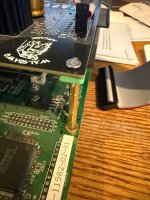
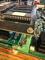
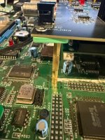
I had some time to kill (at least a week :/) before the new boards get here - I designed some small shims and a brace to mount the sound board above the multi.

I have 50mm standoffs coming and some black m3 flat head screws to make it all match and look nice. Going to print these in ABS-GF as well to be a little stronger than PLA, and match the board.


IMG_2512.jpeg
 

Attachments

  • IMG_2511.jpeg
    IMG_2511.jpeg
    216.7 KB · Views: 13
  • IMG_2509.jpeg
    IMG_2509.jpeg
    188.1 KB · Views: 12
  • IMG_2510.jpeg
    IMG_2510.jpeg
    253 KB · Views: 15
I had some time to kill (at least a week :/) before the new boards get here - I designed some small shims and a brace to mount the sound board above the multi.

I have 50mm standoffs coming and some black m3 flat head screws to make it all match and look nice. Going to print these in ABS-GF as well to be a little stronger than PLA, and match the board.


IMG_2512.jpeg
FYI, a buddy of mine and a member on here is working on a way to mount the sound board and LCD with the Lions3 case. He’s nearly finished and will probably post soon.
 
How does the volume control work playing Batman Forever? Since the signals go from the multi to the amp board, and then you can drive speakers directly off of the amp board (or send those signals back to the helper board to downmix to mono) - where does volume control happen? Is it in the menu of the game?

answered my own question - yep, volume control is in the game test menu.
 
Admittedly it feels silly to pass the signals through the unamped phono connection but if you run st-v in, along with batman, then you can feed it unamped to the cabinet amp.
Amp would come in extra handy for all games if no cab amp.
 
Back
Top