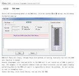
Oh man this was so cool.
ack is the human working to update and document the diagnostics bios. also an absolute genius and taught me to read mempry maps for fault finding.
To trace the remaining fault in slot 4 I looked at the memory map from slot 3 and slot 4 and compared.
The 4th bit is wrong (stuck high) on slot 4. That 4th bit is addressed by d3 which is pin A8 on the prog board
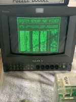
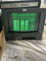
Working backwards I traced address line D3 which is pin A8 on the prog board for each slot
Slot 4 PROG A8 to NeoG0@D1 pin1 = continuity
Slot 3 PROG A8 to NeoG0@D1 pin9 = continuity
Slot 2 PROG A8 to NeoG0@B1 pin21 = continuity
Slot 1 PROG A8 to NeoG0@B1 pin1 = continuity
So all the D3 lines are making it from their NEO-G0 to the slot OK
For slot 3 and 4 it looks like the NEOG0 @D1 splits out the signal it gets on pin 5 and sends it to pin 1 (for slot4) and pin 9 (slot 3)
NeoG0@D1 pin 5 goes to CN10 pin A7 on the top board = continuity
So the D3 line is making is making it from the top board connector to the NEO-GO@D1 OK
CN10A7 on the top board goes to CN10A7 on the bottom board = continuity
So the D3 line is making it from the bottom board to the top board OK
CN10A7 on the bottom board goes to pin 5 of the AS245 at C11 on the bottom board
So the D3 line is making it from the AS245 at C11 to the bottom board connector OK
All of the input pins on the AS245@C11 (13-20) are wired directly to the bios pins 12-19 = continuity
So the D3 line is making it from the BIOS to the AS245@C11 OK
All the traces are good - really that leaves me with a possible bad AS245@C11 or a possible bad NEO-G0@D1
Changed the AS245 = no improvement (I didnt really expect that there would be, but it was much easier than changing the NEO-G0)
So onto the NEO-G0 at D1
Looking inside the NEO-G0@D1 it looks like it is made of 4 x AS245’s all mashed to together on one chip
https://wiki.neogeodev.org/index.php?title=File:Neo-g0_internal.png
All of the problems seem to be associated with the address lines for slot 4, all of which are switched in what used to be U3 an AS245, before they all got bundled together onto the custom.
The AS245 is an SNK custom chip - furrtek on tindle makes replacements, but I was able to borrow one of the MV4F with the z80 problem
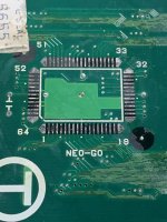
And now, finally, working perfectly. Flawless Victory!
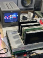
I'll write up my notes properly shortly - before I did that I wanted to say a huge thanks to everyone who has posted in this thread. This project has taught me more about electronics repair than I ever thought possible - thanks team!


 .
.